
Voltage Drop Calculator For 24v Dc Circuit Online | Toolhox
Calculate voltage drop in a 24V DC circuit using current, cable length, and conductor resistance. Estimate load voltage and check cable losses before installation.
Please complete this field to continue.
Please complete this field to continue.
Please complete this field to continue.
Please complete this field to continue.
Please complete this field to continue.
Results
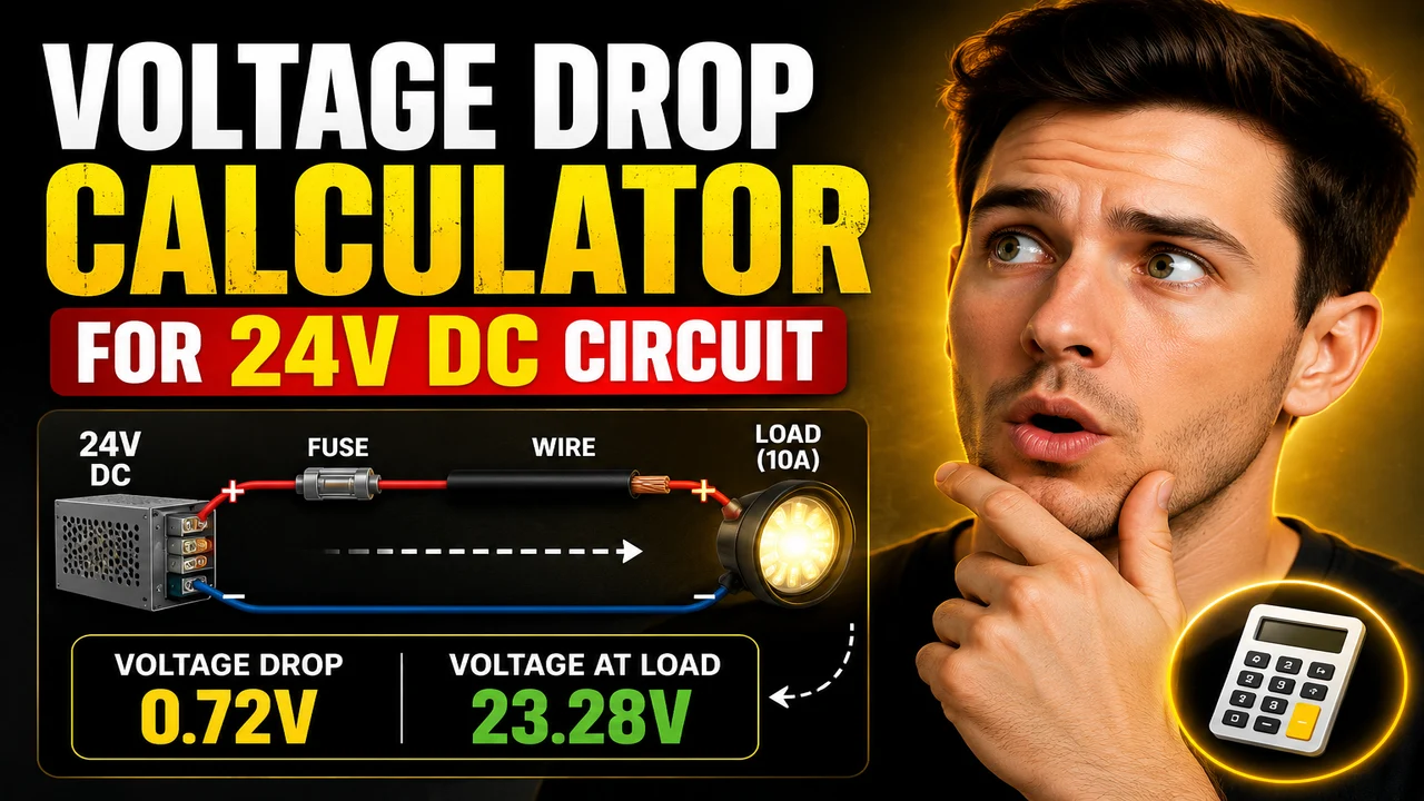
Voltage Drop Calculator For 24v Dc Circuit Online
Quick answer: The Voltage Drop Calculator For 24v Dc Circuit Online helps estimate the voltage lost across conductors in a 24-volt direct-current circuit. Using the circuit current, one-way cable length, and conductor resistance, a DC voltage-drop calculation determines the voltage loss, percentage drop, and estimated voltage available at the load.
A voltage drop calculator for a 24V DC circuit is useful when planning low-voltage power distribution for solar installations, battery-powered equipment, LED lighting, control systems, electronic devices, and other DC applications. Even when the power supply provides a nominal 24 volts, resistance in the positive and return conductors reduces the voltage delivered to the connected equipment.
The amount of voltage lost depends primarily on the current flowing through the circuit, the total resistance of the conductors, and the length of the cable run. Longer cables and higher current generally increase voltage drop. Selecting a conductor with lower resistance can reduce this loss.
TL;DR / Key Takeaways
- Primary Function: Estimate voltage loss in a 24V DC circuit.
- Key Parameters: Circuit voltage, current, cable length, and conductor resistance or wire size, as applicable to the calculator.
- Core Results: Voltage drop in volts, percentage voltage drop, and estimated load voltage can be derived from the calculation.
- Best Suited For: Preliminary wire selection and voltage-loss checks for low-voltage DC installations.
How to Use Voltage Drop Calculator For 24v Dc Circuit Online?
- Set the circuit voltage: Use 24 volts for a nominal 24V DC power system.
- Enter the current: Specify the expected operating current in amperes (A).
- Provide the cable length: Enter the one-way distance between the power source and the load, using the length unit requested by the calculator.
- Specify conductor resistance or wire size: Use the resistance value or conductor selection supported by the tool.
- Calculate and review: Check the estimated voltage drop and compare it with the supply voltage and the load's operating requirements.
Use the actual calculator fields and options displayed on the page. The steps above describe the standard calculation workflow; the specific input controls and output fields depend on the implemented tool.
Input and Output Example
Consider a 24V DC circuit supplying a 10A load through a two-wire copper cable. The source-to-load distance is 20 feet, and the approximate conductor resistance is 1.24 ohms per 1,000 feet for the selected wire under the assumed resistance conditions.
Example Inputs
| Parameter | Example Value | Unit |
|---|---|---|
| Supply voltage | 24 | V DC |
| Load current | 10 | A |
| One-way cable length | 20 | ft |
| Conductor resistance | 1.24 | Ω per 1,000 ft |
| Circuit configuration | Two-wire DC | Positive and return conductors |
Expected Calculation
For a two-wire DC circuit:
Voltage Drop = 2 × Current × Resistance per 1,000 ft × One-Way Length ÷ 1,000
Voltage Drop = 2 × 10 × 1.24 × 20 ÷ 1,000 = 0.496 V
Percentage Drop = (0.496 ÷ 24) × 100 = 2.07%
Load Voltage = 24 − 0.496 = 23.504 V
Example Results
| Result | Calculated Value |
|---|---|
| Voltage drop | 0.496 V |
| Percentage voltage drop | 2.07% |
| Estimated load voltage | 23.504 V |
Example limitation: These are illustrative calculations, not a claim about the calculator's live output. The resistance value is an assumption; actual resistance depends on conductor size, material, temperature, and cable specifications.
Voltage Drop Formula for a 24V DC Circuit
For a two-wire DC circuit with equal-length positive and return conductors, the resistive voltage drop is calculated using Ohm's law:
Vdrop = 2 × I × L × R
When resistance is expressed in ohms per 1,000 feet, use:
Vdrop = (2 × I × L × R1000) ÷ 1,000
Where:
- Vdrop: Voltage lost across the cable pair, in volts (V).
- I: Load current, in amperes (A).
- L: One-way cable distance, in feet (ft).
- R: Resistance per unit length of one conductor, in ohms per foot (Ω/ft).
- R1000: Resistance of one conductor in ohms per 1,000 feet (Ω/1,000 ft).
- 2: Accounts for the outgoing and return conductors.
The percentage voltage drop is:
Voltage Drop (%) = (Vdrop ÷ Vsupply) × 100
The estimated voltage at the load is:
Vload = Vsupply − Vdrop
For a nominal 24V supply, the percentage calculation uses 24V as the reference voltage. If the actual source voltage varies with battery state, charging conditions, or power-supply regulation, use the relevant operating voltage for a more representative assessment.
24V DC Voltage Drop Reference Table
The following table shows illustrative voltage-drop targets for a nominal 24V DC supply. These are mathematical reference values, not universal installation limits.
| Voltage Drop Target | Voltage Lost | Remaining Load Voltage |
|---|---|---|
| 1% | 0.24 V | 23.76 V |
| 2% | 0.48 V | 23.52 V |
| 3% | 0.72 V | 23.28 V |
| 4% | 0.96 V | 23.04 V |
| 5% | 1.20 V | 22.80 V |
Choose a target based on the equipment manufacturer's permitted input-voltage range, the applicable electrical requirements, and the circuit's operating conditions. A percentage target alone does not establish that a cable installation is safe or adequately sized.
How Cable Length, Current, and Wire Size Affect Voltage Drop
Cable length: With the same conductor resistance and current, doubling the one-way cable distance doubles the calculated voltage drop. The formula already accounts for both conductors through its factor of two, so enter the one-way distance when that is what the calculator requests.
Load current: Voltage drop increases in direct proportion to current for a fixed conductor resistance and cable length. A circuit drawing 20A has twice the resistive voltage drop of the same circuit drawing 10A, assuming the conductor resistance remains unchanged.
Wire size: A larger conductor generally has lower resistance per unit length than a smaller conductor of the same material. Lower resistance reduces voltage drop, although the final conductor selection must also account for current-carrying capacity, installation method, insulation temperature rating, protection, and applicable regulations.
Conductor material and temperature: Copper and aluminum have different electrical resistivities. Resistance also rises with conductor temperature. Calculations using a room-temperature resistance value may underestimate losses when the conductor operates at a higher temperature.
Technical Reference: Inputs and Their Effects
| Input or Condition | Effect on Calculated Drop | Practical Consideration |
|---|---|---|
| Supply voltage | Does not directly change the absolute drop when current, resistance, and length are fixed; it changes the percentage drop. | Use the relevant operating supply voltage. |
| Load current | Higher current produces a proportionally higher drop. | Use expected operating current and account for relevant peak loads. |
| One-way length | Longer cable increases drop proportionally. | Measure the source-to-load distance, not the round-trip distance, if the formula includes a factor of two. |
| Conductor resistance | Higher resistance increases drop proportionally. | Use resistance data for the selected cable and operating conditions. |
| Wire cross-sectional area | Increasing conductor area generally reduces resistance and drop. | Confirm both voltage-drop performance and current-carrying capacity. |
| Temperature | Higher conductor temperature generally increases resistance. | Use temperature-adjusted resistance when greater accuracy is required. |
Edge Cases and Limitations
- Zero current: The ideal resistive voltage drop is zero when no current flows, although real-world measurement conditions may differ.
- Zero length: The ideal cable-related drop is zero for a zero-length conductor pair; connectors and other circuit components can still introduce losses.
- Negative inputs: Negative cable lengths, resistance values, or operating currents are not appropriate for ordinary cable-sizing calculations and should be checked before using a result.
- Round-trip length entered incorrectly: If the formula already doubles one-way length, entering the total positive-plus-return distance will double-count cable length.
- Resistance assumptions: Generic resistance values may not represent a specific cable's construction, temperature, or condition.
- Transient loads: Startup current and short-duration peaks may cause more voltage drop than a steady-state calculation predicts.
- Parallel conductors and unusual returns: Multiple conductors, chassis returns, unequal cable lengths, and complex wiring configurations require an appropriate circuit model rather than an unmodified two-wire formula.
The exact validation rules, supported wire-size standards, material choices, automatic wire-sizing functions, and output precision of this specific online tool have not been established from the supplied tool details. Check the actual interface before assuming that it supports any particular option.
Technical Accuracy and Safety
A voltage-drop calculation is one part of conductor selection. It does not, by itself, confirm that a cable can safely carry the required current or that the circuit meets all applicable installation requirements. Verify conductor ampacity, fuse or breaker sizing, insulation ratings, terminal limits, environmental conditions, and the load manufacturer's voltage requirements before installation.
For additional technical context, consult the International Association of Electrical Inspectors' voltage-drop formulas article and the Southwire Voltage Drop Calculator. These references explain established voltage-drop calculation methods and conductor-selection considerations; they do not verify the implementation of this particular tool.
Technical Disclaimer: Results are preliminary engineering estimates based on the formula and input assumptions. Validate the final conductor selection against manufacturer data, applicable electrical codes, installation conditions, and qualified electrical engineering judgment.
Author and Technical Review
Author Name: Daniel Mercer
Author Description: Electrical engineering content specialist focused on DC power distribution, conductor resistance, and low-voltage circuit calculations.
Technical Review: The calculation methodology presented here is based on Ohm's law and the round-trip resistance of a two-wire DC circuit. The example arithmetic and assumptions should be checked against the actual calculator implementation before being treated as a verified test of the tool.
