
Voltage Drop Calculator For Landscape Lighting Wire
Use the Voltage Drop Calculator For Landscape Lighting Wire to estimate cable voltage loss from load, distance, and wire gauge before planning your lighting run.
Please complete this field to continue.
Please complete this field to continue.
Please complete this field to continue.
Please complete this field to continue.
Please complete this field to continue.
Results
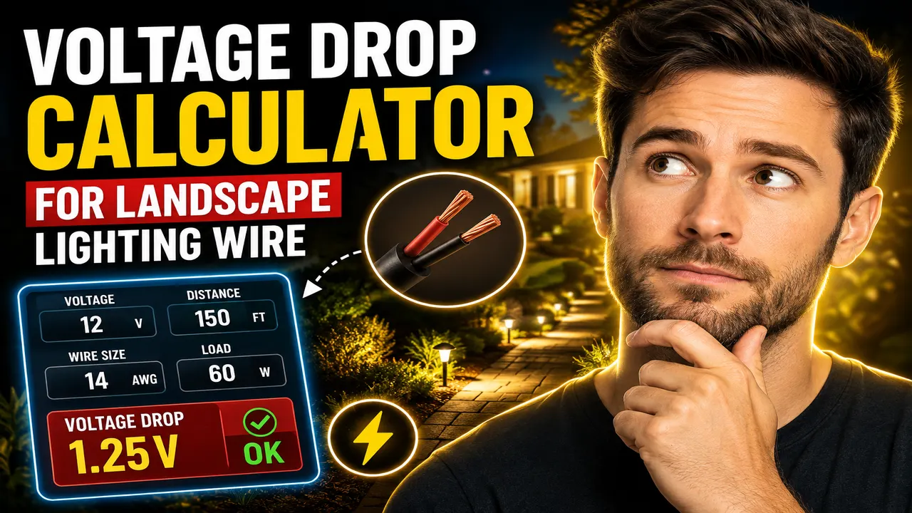
Voltage Drop Calculator For Landscape Lighting Wire
Quick answer: The Voltage Drop Calculator For Landscape Lighting Wire is an electrical calculator concept for estimating voltage lost along a landscape lighting cable. With the appropriate supply voltage, load current or fixture wattage, one-way cable length, and wire resistance or gauge, a calculation can estimate voltage drop, percentage drop, and voltage remaining at the fixtures. The exact inputs and outputs depend on the calculator's implemented features.
Low-voltage landscape lighting often uses long cable runs to connect a transformer with outdoor LED fixtures, path lights, spotlights, and garden lights. As current travels through a wire, the conductor's electrical resistance reduces the voltage available at the fixtures. If the voltage loss is too high, distant lights may operate at a lower voltage than intended, and brightness or performance may vary across the installation.
The Voltage Drop Calculator For Landscape Lighting Wire helps explain this design consideration by relating the electrical load, cable distance, and conductor resistance. It is intended for landscape lighting planning, preliminary wire-gauge comparisons, and understanding why a longer cable or heavier load can require a thicker conductor. The calculations below describe a standard two-conductor, direct-current voltage-drop method; they should be matched to the actual calculator implementation before publication as verified tool behavior.
Why Does Voltage Drop Matter in Landscape Lighting?
Landscape lighting systems commonly distribute power at low voltages, such as 12 V or 24 V. At lower supply voltages, even a modest loss represents a relatively large percentage of the available voltage. For example, a 1 V loss is approximately 8.33% of a 12 V supply but only 4.17% of a 24 V supply.
- Long cable runs: More conductor length means more resistance and usually more voltage loss.
- Higher electrical loads: More current produces a larger voltage drop across the same wire.
- Wire gauge: A lower AWG number generally indicates a thicker conductor with lower resistance.
- Fixture placement: Lights near the end of a long run can receive less voltage than lights close to the transformer.
- Wiring layout: A daisy-chain, hub, or individual home-run layout can distribute current differently and affect the voltage delivered to each fixture.
Key Takeaways
- Primary function: Estimate voltage loss in landscape lighting cable.
- Important variables: Supply voltage, current, one-way cable length, conductor resistance, and wire size.
- Useful results: Voltage drop in volts and as a percentage of source voltage, plus estimated load voltage.
- Best suited for: Preliminary planning of low-voltage landscape lighting cable runs.
How to Use Voltage Drop Calculator For Landscape Lighting Wire?
Use the following workflow if the calculator provides the corresponding fields. Confirm the actual input labels and available options in the published interface.
- Identify the supply voltage. Enter the transformer output voltage used for the lighting circuit, such as 12 V or 24 V.
- Determine the connected load. Use the total fixture wattage or the actual current drawn by the circuit. If wattage is provided, current can be estimated by dividing total watts by supply voltage for a simple DC load.
- Measure the one-way cable distance. Measure the cable route from the source to the load, including the path around landscaping, buildings, and obstacles.
- Select the conductor. Choose the actual wire gauge and conductor material, or use the conductor resistance value if the interface requests it.
- Calculate and inspect the result. Review the estimated voltage drop and remaining voltage. Compare the result with the fixture manufacturer's operating-voltage requirements and the design target for the installation.
What Do the Inputs Mean?
| Parameter | Unit | Purpose |
|---|---|---|
| Supply voltage | V | Voltage provided by the transformer or power source. |
| Total fixture wattage | W | Combined rated power of the fixtures connected to the circuit. |
| Load current | A | Current flowing through the cable section being evaluated. |
| One-way cable length | ft or m | Distance from the supply to the load along the cable route. |
| Wire gauge | AWG | Conductor size; smaller AWG numbers usually mean thicker wire. |
| Conductor resistance | Ω/1,000 ft or Ω/km | Resistance used to estimate the voltage lost in the wire. |
Voltage Drop Formula for Landscape Lighting Wire
For a simple two-conductor DC circuit using a constant current and a conductor resistance expressed per unit length, the voltage-drop formula is:
Voltage Drop (V) = 2 × L × I × R / 1000
This version applies when L is the one-way length in feet and R is the conductor resistance in ohms per 1,000 feet. The factor of 2 accounts for the outgoing and return conductors.
- L: One-way cable length in feet.
- I: Current through the cable section, in amperes.
- R: Conductor resistance in ohms per 1,000 feet.
- 2: Factor accounting for the round-trip conductor length.
For a source voltage of Vs, the percentage drop is:
Voltage Drop (%) = Voltage Drop (V) ÷ Vs × 100
The estimated voltage at the load is:
Load Voltage (V) = Source Voltage − Voltage Drop
If the load is specified in watts, a first-order current estimate for a DC lighting load is:
Current (A) ≈ Total Load (W) ÷ Supply Voltage (V)
For multiple fixtures distributed along a cable, the current is not necessarily the same throughout the entire run. The simple formula using the full load current over the full length represents a conservative arrangement when the entire load is effectively at the end. A distributed-load or branch-by-branch calculation may produce a different result.
Worked Example: 12 V Landscape Lighting
Consider a hypothetical circuit with 60 W of connected lighting, a 12 V DC source, a 50 ft one-way run, and 12 AWG copper wire. For this example, assume a conductor resistance of 1.62 Ω per 1,000 ft at the reference temperature. These are illustrative calculation inputs, not a claim about the tool's default settings.
| Input | Value |
|---|---|
| Source voltage | 12 V |
| Total load | 60 W |
| Estimated current | 60 ÷ 12 = 5 A |
| One-way cable length | 50 ft |
| Wire gauge | 12 AWG copper |
| Reference resistance | 1.62 Ω/1,000 ft |
Step 1 — Calculate voltage drop:
Voltage drop = 2 × 50 × 5 × 1.62 ÷ 1000 = 0.81 V
Step 2 — Calculate percentage drop:
Percentage drop = 0.81 ÷ 12 × 100 = 6.75%
Step 3 — Estimate voltage at the load:
Load voltage = 12 − 0.81 = 11.19 V
This simplified example predicts approximately 0.81 V of drop at the end of the run. Whether 11.19 V is acceptable depends on the actual fixture's rated input range, transformer output under load, cable temperature, wiring topology, and the project's voltage-drop target.
Wire Gauge Reference for Landscape Lighting
The following reference values are approximate resistance figures for copper conductors at a reference temperature near 20–25°C. Actual resistance varies by conductor construction, temperature, manufacturing tolerance, and the reference table used. Verify the cable specification for a final design.
| Copper Wire Gauge | Approx. Resistance (Ω/1,000 ft) | Relative Voltage-Drop Tendency |
|---|---|---|
| 10 AWG | 1.02 | Lowest among these examples |
| 12 AWG | 1.62 | Low |
| 14 AWG | 2.58 | Higher |
| 16 AWG | 4.09 | Highest among these examples |
For the same current and cable distance, voltage drop is proportional to conductor resistance. Using the values above, a 16 AWG conductor has about four times the resistance of a 10 AWG conductor. Consequently, selecting a thicker wire can substantially reduce voltage loss on long landscape-lighting runs.
How to Interpret the Results
Use both the voltage-drop percentage and the calculated voltage at the fixture. A percentage alone does not establish whether a particular LED driver or landscape fixture will operate correctly.
- Small voltage drop: The load receives a voltage closer to the source voltage, all else being equal.
- Large voltage drop: Consider a thicker conductor, a shorter run, a revised branching layout, or a properly designed alternative supply arrangement.
- Voltage below the fixture's rated range: Review the transformer tap, total load, wire sizing, connections, and fixture specifications before installation.
- Uneven brightness: Check whether the fixtures are distributed along the run and whether each cable segment carries a different current.
There is no universal percentage that guarantees correct performance for every landscape lighting system. A target such as 3% or 5% may be used for a particular design objective, while some low-voltage landscape installations use a different allowable drop based on the equipment and manufacturer's guidance. Do not treat any single target as a substitute for fixture specifications.
Edge Cases and Limitations
- Zero current: The ideal resistive voltage-drop calculation returns zero when no current flows.
- Zero cable length: The idealized cable drop is zero when the conductor length is zero, though real connections and leads may still contribute resistance.
- Negative inputs: Negative physical length, negative load wattage, or negative resistance are generally invalid for ordinary cable sizing.
- Distributed fixtures: Using total current for the entire run can overestimate or misrepresent drop when fixtures draw current at different positions along the cable.
- Temperature: Copper resistance increases as conductor temperature rises, so room-temperature values may understate drop in warmer operating conditions.
- AC transformers and drivers: A DC resistance calculation is a simplified model. AC characteristics, transformer regulation, driver behavior, and power factor may require a different method.
- Material and wire type: Copper reference values must not be used for aluminum or an unspecified conductor without an appropriate resistance value.
- Multiple branches: Each branch should be assessed using the current and length for that branch rather than assuming one identical current across every section.
The actual calculator's supported inputs, wire-gauge options, validation behavior, and output fields must be confirmed from its live implementation. The formula and examples here are engineering references, not proof that every listed feature is currently exposed by the interface.
Technical References
- Southwire Voltage Drop Calculator — a reference for conductor sizing and voltage-drop calculations.
- Southwire Calculators — manufacturer-provided electrical calculation resources.
Technical Disclaimer: This calculation provides a preliminary estimate based on simplified conductor-resistance assumptions. It does not verify conductor ampacity, transformer capacity, cable suitability for direct burial, waterproof connections, electrical-code compliance, or fixture compatibility. Confirm the cable and fixture specifications, installation requirements, and applicable local regulations before installing landscape lighting.
Author: Daniel R. Mitchell
Author Description: Electrical Systems Engineer specializing in low-voltage power distribution, conductor sizing, and lighting-system design.
Technical Review: The formula, units, round-trip conductor factor, worked example, and reference assumptions should be checked against the actual calculator implementation and the selected cable manufacturer's resistance data before publication.
