
Voltage Across Capacitor Calculator Differential | Toolhox
Calculate capacitor voltage from an RC differential equation using resistance, capacitance, time, and initial/final voltage values. Review the formula and result.
Please complete this field to continue.
Please complete this field to continue.
Please complete this field to continue.
Please complete this field to continue.
Please complete this field to continue.
Results
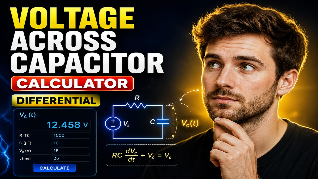
Voltage Across Capacitor Calculator Differential
Quick answer: The Voltage Across Capacitor Calculator Differential is an electrical engineering calculator for determining the voltage across a capacitor as it charges or discharges in a first-order RC circuit. It uses the capacitor voltage differential equation, resistance, capacitance, elapsed time, and initial and final voltage conditions to calculate the transient voltage response.
Capacitor voltage changes over time when current flows into or out of a capacitor. In a resistor-capacitor (RC) circuit, the rate of this change depends on the resistance, capacitance, and applied voltage. The differential equation provides a mathematical model for analyzing this behavior.
The Voltage Across Capacitor Calculator Differential is intended for students, electronics learners, electrical engineers, and circuit designers who need to evaluate capacitor voltage during transient conditions. It connects the differential equation to the exponential response commonly observed in first-order RC circuits.
TL;DR / Key Takeaways
- Primary Function: Calculate capacitor voltage as a function of time using an RC differential-equation model.
- Key Parameters: Resistance, capacitance, elapsed time, initial capacitor voltage, and final steady-state voltage.
- Core Output: Calculated capacitor voltage in volts.
- Important Relationship: The RC time constant is τ = RC.
- Best Suited For: RC circuit analysis, electronics coursework, and transient-response calculations.
How to Use Voltage Across Capacitor Calculator Differential?
For a first-order RC circuit, the capacitor voltage can be calculated from the circuit's resistance, capacitance, elapsed time, and voltage boundary conditions. Use the following workflow when these parameters are available in the calculator.
- Enter the resistance: Supply the resistance R in ohms (Ω). Resistance affects how quickly the capacitor charges or discharges.
- Enter the capacitance: Supply the capacitance C in farads (F), or use a supported subunit such as microfarads (µF) after converting it to farads if necessary.
- Specify the time: Enter the elapsed time t in seconds (s), measured from the beginning of the transient event.
- Provide voltage conditions: Specify the initial capacitor voltage and the final steady-state voltage when the calculation uses the general RC response equation.
- Calculate and review: Evaluate the voltage response and check that the units and assumed circuit conditions are consistent.
The exact input fields and output presentation depend on the calculator implementation. The equations and examples below describe the standard first-order RC model rather than guaranteeing a particular interface or additional feature.
Input and Output Example
Consider a capacitor charging toward a 12 V supply through a 10 kΩ resistor. The capacitor initially has zero voltage, its capacitance is 100 µF, and the elapsed time is 1 second.
Example Input
- Supply or final voltage: 12 V
- Resistance: 10,000 Ω
- Capacitance: 0.0001 F (100 µF)
- Initial capacitor voltage: 0 V
- Elapsed time: 1 s
Calculation
The time constant is:
τ = RC
τ = 10,000 × 0.0001 = 1 second
For an initially uncharged capacitor charging toward a constant 12 V supply:
VC(t) = VS(1 − e−t/RC)
Substituting the values:
VC(1) = 12(1 − e−1)
VC(1) ≈ 12 × 0.6321
Calculated capacitor voltage ≈ 7.59 V
This is the expected theoretical voltage for an ideal first-order RC charging circuit at one time constant. It is an illustrative calculation, not a claim that the live calculator has been executed with these values.
Differential Equation for Capacitor Voltage
The fundamental relationship for an ideal capacitor is:
iC(t) = C × dVC(t)/dt
Where:
- iC(t): Instantaneous capacitor current in amperes (A).
- C: Capacitance in farads (F).
- VC(t): Voltage across the capacitor in volts (V).
- dVC/dt: Rate of change of capacitor voltage in volts per second (V/s).
For a series RC circuit driven by a constant voltage source VS, Kirchhoff's voltage law gives:
VS = VR + VC
Using Ohm's law, VR = Ri, and the capacitor current relation, the differential equation becomes:
RC × dVC/dt + VC = VS
For constant resistance, constant capacitance, and a constant source voltage, the solution is:
VC(t) = VS + [VC(0) − VS]e−t/RC
This general expression accounts for a nonzero initial capacitor voltage. It describes charging toward a higher final voltage and discharging toward a lower final voltage, provided the circuit follows the assumed first-order RC model.
Formula Variables and Units
| Symbol | Meaning | SI Unit |
|---|---|---|
| VC(t) | Capacitor voltage at time t | Volt (V) |
| VC(0) | Initial capacitor voltage | Volt (V) |
| VS | Constant applied source voltage | Volt (V) |
| R | Resistance | Ohm (Ω) |
| C | Capacitance | Farad (F) |
| t | Elapsed time | Second (s) |
| τ = RC | RC time constant | Second (s) |
Charging and Discharging Reference Table
The following reference values apply to ideal first-order RC circuits. They express the capacitor voltage as a fraction of the total voltage change after a given number of time constants.
| Elapsed Time | Charging Progress | Remaining Discharge Voltage |
|---|---|---|
| 0τ | 0% | 100% |
| 0.5τ | 39.35% | 60.65% |
| 1τ | 63.21% | 36.79% |
| 2τ | 86.47% | 13.53% |
| 3τ | 95.02% | 4.98% |
| 4τ | 98.17% | 1.83% |
| 5τ | 99.33% | 0.67% |
How to interpret the table: Charging progress is the fraction of the difference between the initial and final voltages that has been completed. Remaining discharge voltage is the fraction of the initial voltage difference that remains during discharge toward zero. These percentages are theoretical reference values, rounded for readability.
How the RC Time Constant Affects Voltage
The time constant, τ = RC, determines the characteristic speed of the voltage response. A larger resistance or capacitance increases the time constant, causing the capacitor voltage to approach its final value more slowly. A smaller time constant produces a faster response.
- Small RC time constant: Voltage changes relatively quickly.
- Large RC time constant: Voltage changes relatively slowly.
- At one time constant: The capacitor completes approximately 63.2% of the total voltage change.
- At five time constants: The capacitor has completed approximately 99.3% of the total voltage change in the ideal model.
These percentages apply to the normalized first-order response. They do not mean that every circuit reaches exactly 63.2% or 99.3% of a particular supply voltage unless the initial and final voltage conditions match the assumed model.
Edge Cases and Limitations
Initial Voltage Is Not Zero
A capacitor may already contain stored charge before a switching event. Use the general equation with VC(0) rather than assuming an initially uncharged capacitor. The simplified charging expression VS(1 − e−t/RC) applies only when the initial voltage is zero and the final voltage is VS.
Zero Resistance or Zero Capacitance
The standard RC time constant is τ = RC. If either parameter is zero, the usual exponential model with a positive time constant no longer describes an ordinary physical RC transient. An ideal zero-resistance source connection can imply an instantaneous voltage change, which is not a realistic model of parasitic circuit behavior.
Negative Time
Elapsed time in the ordinary charging or discharging calculation should be nonnegative and measured from the defined initial condition. Negative time generally represents a different mathematical interval and should not be interpreted as a normal forward-time transient without an explicit model.
Unit Conversion
Use consistent SI units when evaluating the equation. For example, 10 kΩ must be converted to 10,000 Ω, and 100 µF must be converted to 0.0001 F. Mixing kilohms, microfarads, milliseconds, and seconds without conversion can produce incorrect results.
Non-Ideal Circuits
The standard equation assumes a linear resistor, constant capacitance, a constant source voltage, and a first-order circuit. Inductors, nonlinear components, changing sources, capacitor leakage, equivalent series resistance, and additional circuit branches can change the response. Circuits with multiple energy-storage elements may require a higher-order differential equation.
Technical Disclaimer: This page explains the standard mathematical model for capacitor voltage in first-order RC circuits. Verify circuit topology, initial conditions, component tolerances, voltage ratings, and transient behavior before using a calculated value for hardware design or safety-critical engineering decisions.
Author Information
Author: Daniel Mercer
Author Description: Electrical engineering technical writer focused on circuit analysis, electronics fundamentals, and engineering calculations.
Technical Review: The equations and worked example are presented using the conventional first-order RC model and standard capacitor current-voltage relationship. Results should be checked against the actual circuit configuration and its boundary conditions.
Authoritative References
- OpenStax University Physics Volume 2: RC Circuits — explains capacitor voltage, Kirchhoff's loop rule, and the differential equation for RC charging and discharging.
- Georgia Tech Physics Book: Charging and Discharging a Capacitor — provides the RC transient equations and the physical interpretation of the time constant.
