
Voltage Source To Current Source Transformation Calculator
Convert voltage and series resistance into an equivalent current source with parallel resistance using the voltage source to current source transformation formula.
Please complete this field to continue.
Please complete this field to continue.
Results
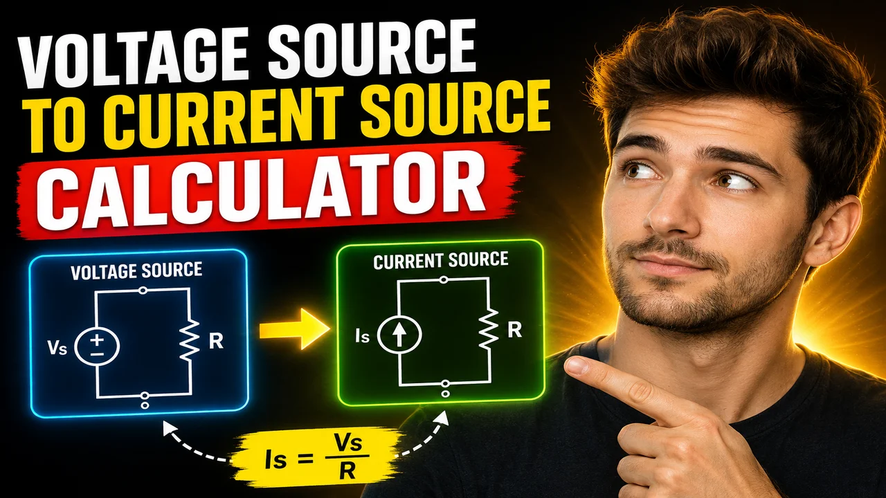
Voltage Source To Current Source Transformation Calculator
The Voltage Source To Current Source Transformation Calculator converts a practical voltage source into an equivalent current source using the source voltage and series resistance. It applies the electrical source transformation principle used in circuit analysis to represent the same two-terminal network in voltage-source or current-source form.
Quick answer: To transform a voltage source into an equivalent current source, divide the source voltage by its series resistance. The equivalent current source is connected in parallel with the same resistance.
TL;DR / Key Takeaways
- Primary Function: Converts a voltage-source and series-resistance pair into a current-source and parallel-resistance pair.
- Key Inputs: Voltage source value in volts (V) and series resistance in ohms (Ω).
- Core Output: Equivalent current in amperes (A) and the resistance retained in parallel.
- Best Suited For: Electrical engineering students, circuit designers, and technicians working with linear circuit networks.
How to Use Voltage Source To Current Source Transformation Calculator?
- Enter the source voltage: Provide the voltage of the practical voltage source in volts (V).
- Enter the series resistance: Specify the resistance connected in series with the voltage source, in ohms (Ω).
- Calculate the equivalent source: Apply the source transformation equation to determine the equivalent current.
- Review the result: Check the calculated current and retain the original resistance value for the parallel current-source representation.
What Inputs Are Required?
| Input | Symbol | Unit | Meaning |
|---|---|---|---|
| Source voltage | V | Volts (V) | The voltage supplied by the ideal voltage source. |
| Series resistance | R | Ohms (Ω) | The resistance connected in series with the voltage source. |
Use voltage and resistance values expressed in compatible units. For example, a voltage entered in volts and a resistance entered in ohms produces current in amperes. If the available values use millivolts, kilovolts, milliohms, or kilo-ohms, convert them to compatible units before calculation unless the calculator explicitly supports unit selection.
Input and Output Example
Consider a practical voltage source with a voltage of 12 V and a series resistance of 4 Ω.
Input
- Source voltage: 12 V
- Series resistance: 4 Ω
Calculation
Equivalent current = Source voltage ÷ Series resistance
I = 12 V ÷ 4 Ω = 3 A
Output
- Equivalent current source: 3 A
- Parallel resistance: 4 Ω
The transformed circuit consists of a 3 A ideal current source in parallel with a 4 Ω resistor. When the original voltage source and the transformed current source are connected to the same external load, both representations produce the same terminal voltage-current relationship, assuming the ideal source-transformation conditions are satisfied.
Voltage-to-Current Source Transformation Formula
The fundamental formula for converting a voltage source into an equivalent current source is:
I = V ÷ R
Where:
- I = equivalent current-source current in amperes (A).
- V = voltage-source voltage in volts (V).
- R = series resistance in ohms (Ω).
The resistance value does not change during the transformation. Its connection changes from series with the voltage source to parallel with the current source.
Why Does the Formula Work?
For a practical voltage source with source voltage V and series resistance R, the terminal voltage under a load current IL can be written as:
Vterminal = V − ILR
For the equivalent current-source circuit, the source current is IS = V/R. Applying Kirchhoff's current law at the output node gives the same terminal relationship when the resistor and source polarity/current direction are represented consistently. Thus, the two circuits are equivalent at their external terminals.
Source Transformation Reference Table
| Source Voltage | Series Resistance | Equivalent Current | Parallel Resistance |
|---|---|---|---|
| 5 V | 10 Ω | 0.5 A | 10 Ω |
| 12 V | 4 Ω | 3 A | 4 Ω |
| 24 V | 8 Ω | 3 A | 8 Ω |
| 9 V | 3 Ω | 3 A | 3 Ω |
| 48 V | 12 Ω | 4 A | 12 Ω |
| 100 V | 20 Ω | 5 A | 20 Ω |
Each row uses I = V/R. These examples illustrate how the source voltage and resistance determine the equivalent current while the resistance magnitude remains unchanged.
How Voltage Source Transformation Works
Source transformation is a circuit-analysis technique that replaces a practical voltage source and its series resistance with a practical current source and a parallel resistance. It is commonly used when simplifying electrical networks, applying Kirchhoff's laws, or preparing a circuit for further analysis using Thevenin's and Norton's theorems.
The transformation preserves the terminal behavior of the source network rather than preserving the internal arrangement of components. The voltage source provides a fixed ideal voltage, while the current-source representation provides an ideal current equal to V/R. In both representations, the resistance determines how the terminal voltage changes as load current changes.
Voltage Source Versus Current Source
| Characteristic | Voltage-Source Form | Current-Source Form |
|---|---|---|
| Ideal source quantity | Voltage, V | Current, I = V/R |
| Resistance connection | Series | Parallel |
| Resistance value | R | Same R |
| External terminal behavior | Equivalent under valid conditions | Equivalent under valid conditions |
Technical Edge Cases and Limitations
Zero Resistance
If R = 0 Ω, the expression I = V/R is undefined for a nonzero voltage. An ideal voltage source with zero series resistance cannot be converted into an ordinary finite current source using this formula. A zero-voltage source with zero resistance is a separate limiting case and should not be handled by blindly dividing zero by zero.
Negative Resistance Values
Ordinary passive source-transformation examples use positive resistance. If a negative resistance appears in an active circuit model, the mathematical relationship may still be analyzed in a suitable model, but its physical meaning and stability require additional consideration. Confirm that the calculator is intended to accept such values before relying on a result.
Current Direction and Voltage Polarity
The magnitude of the equivalent current is V/R. Its direction depends on the chosen reference polarity of the voltage source. When redrawing a circuit, keep the current-source arrow consistent with the voltage polarity and terminal convention. Reversing the reference direction changes the sign of the represented current.
Unit Consistency and Rounding
Divide voltage by resistance using compatible SI units. For example, 12 V divided by 4 kΩ is 0.003 A, or 3 mA—not 3 A. Round the displayed current only after performing the calculation, because premature rounding can affect subsequent circuit calculations.
Ideal and Practical Models
Source transformation is valid for a linear two-terminal source network represented by a voltage source in series with a resistance and its equivalent current source in parallel with that resistance. It does not mean that an arbitrary nonlinear circuit can always be replaced by one ideal source and one resistor. For AC circuits, the corresponding relationship can use complex impedance and phasor quantities, but a calculator based on real voltage and resistance inputs should not be assumed to support that extension.
Technical Reference and Further Reading
- OpenStax University Physics, Volume 2 — background in electric circuits and electrical principles.
- All About Circuits: Source Transformations — a focused explanation of source transformation in circuit analysis.
Frequently Asked Questions
What is the formula for voltage source to current source transformation?
The equivalent current is I = V/R, where V is the voltage-source value and R is the series resistance. The same resistance value is connected in parallel with the equivalent current source.
Does resistance change during source transformation?
No. The resistance magnitude remains the same. Only its connection changes from series with the voltage source to parallel with the current source.
Can a voltage source with zero series resistance be transformed?
Not into a finite current source using I = V/R when R is zero and V is nonzero. The division is undefined, so the ideal-source limiting case must be treated separately.
How do I determine the direction of the equivalent current source?
Use the voltage-source polarity and the chosen terminal reference. The current-source arrow must be selected so that the transformed circuit reproduces the original terminal voltage-current relationship.
Can I use kilo-ohms or milliamperes?
Yes, if the values are converted consistently. For example, 12 V divided by 4 kΩ equals 3 mA. Mixing volts and kilo-ohms while interpreting the result as amperes leads to a factor-of-1,000 error.
Is source transformation the same as Thevenin-to-Norton conversion?
It is the same fundamental equivalence when applied to a linear two-terminal source network: a Thevenin voltage source with series resistance corresponds to a Norton current source with parallel resistance, with IN = VTh/RTh.
Technical Disclaimer: This calculator's formula is intended for idealized linear source models. Verify source polarity, resistance units, and the assumptions of the circuit before using calculated values in practical electrical designs or safety-critical work.
Author: Michael Turner, Electrical Engineering Specialist
Author Description: Electrical engineering content specialist focused on circuit analysis, source equivalence, and fundamental electrical calculations.
Technical Review: The source-transformation methodology is based on the terminal-equivalence relationship between a linear voltage source with series resistance and a current source with parallel resistance. Verify the implementation's supported inputs and output conventions before publishing tool-specific behavior.
