
Voltage Divider Calculator With Op Amp Output Calc
Calculate voltage divider output and estimate op-amp voltage from resistor values and input voltage. Review formulas, circuit assumptions, and practical limits.
Please complete this field to continue.
Please complete this field to continue.
Please complete this field to continue.
Please complete this field to continue.
Please complete this field to continue.
Please complete this field to continue.
Results
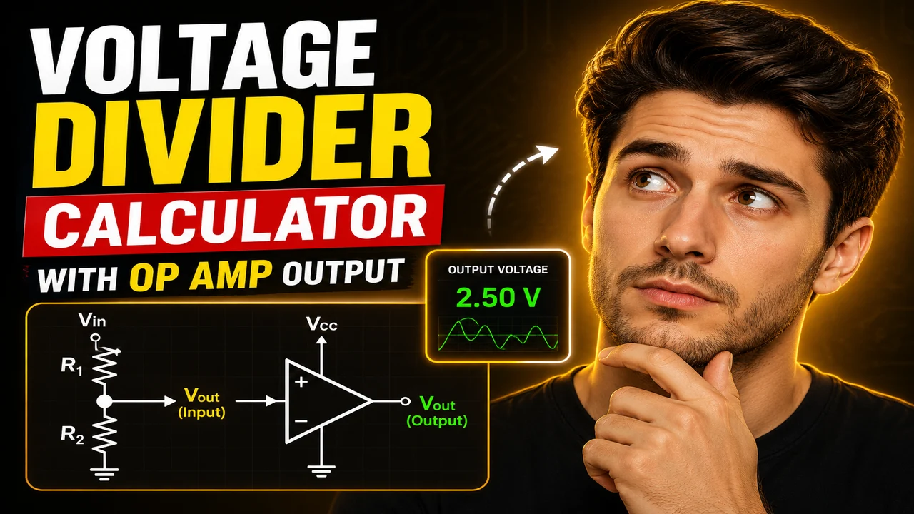
Voltage Divider Calculator With Op Amp Output Calc
Quick answer: The Voltage Divider Calculator With Op Amp Output Calc is an electrical engineering calculator for determining a voltage divider's output voltage and evaluating an op-amp output based on circuit inputs. It is intended to help students, electronics hobbyists, and engineers analyze resistor-divider circuits and understand how a connected operational amplifier affects the signal.
TL;DR / Key Takeaways
- Primary Function: Calculate voltage divider output and analyze an op-amp output.
- Key Inputs: Supply or input voltage, resistor values, and circuit parameters required by the selected op-amp configuration.
- Core Output: Calculated divider voltage and, where the necessary circuit details are provided, an estimated op-amp output voltage.
- Best Suited For: Voltage reference design, resistor-divider analysis, introductory analog electronics, and preliminary circuit calculations.
How to Use Voltage Divider Calculator With Op Amp Output Calc?
- Enter the input or supply voltage used by the voltage divider.
- Enter the upper and lower resistor values, keeping their units consistent.
- Provide the additional circuit parameters required for the op-amp configuration being evaluated.
- Run the calculation and review the resulting voltage values against your circuit requirements.
What Is a Voltage Divider?
A voltage divider uses two or more series-connected resistors to produce a fraction of an applied voltage. For a conventional two-resistor divider, the output is measured across the lower resistor when the reference node is ground. The resulting voltage depends on the resistor ratio rather than the absolute resistance values, provided the divider is unloaded or its loading is negligible.
This arrangement is commonly used to establish reference levels, scale sensor signals, and provide a suitable input voltage for an analog circuit. The divider's output can change when a connected circuit draws current, so the distinction between an unloaded divider and a loaded divider matters in practical designs.
What Does the Op-Amp Output Calculation Represent?
An operational amplifier (op amp) can buffer, amplify, compare, or otherwise process a divider voltage, depending on its circuit configuration. A voltage follower, for example, is designed to reproduce its input voltage approximately while providing a lower output impedance. An amplifier with feedback may instead scale the input according to its closed-loop gain.
The divider voltage alone is not enough to determine every op-amp output. The circuit topology, resistor network, supply rails, feedback arrangement, input common-mode range, output swing, and device characteristics can all affect the real result. Use the calculation that matches the actual circuit rather than assuming that every op amp simply reproduces the divider voltage.
Input and Output Example
Example: Unloaded Voltage Divider
Suppose a 12 V source is connected to a 10 kΩ upper resistor and a 20 kΩ lower resistor. The output is measured at the junction between the resistors and ground.
| Parameter | Example value |
|---|---|
| Input voltage | 12 V |
| Upper resistor (R1) | 10 kΩ |
| Lower resistor (R2) | 20 kΩ |
| Expected divider output | 8 V |
The output is calculated as:
Vout = Vin × R2 / (R1 + R2)
Vout = 12 × 20 / (10 + 20) = 8 V
For an ideal voltage follower connected to this node, the expected output is approximately 8 V, provided the op amp's supply voltage, input common-mode range, output swing, and other operating conditions allow it.
Voltage Divider Formula and Methodology
The standard two-resistor voltage divider equation is:
Vout = Vin × R2 / (R1 + R2)
- Vin: Voltage applied across the complete series resistor pair, measured in volts (V).
- R1: Upper resistor between the input source and the output node.
- R2: Lower resistor between the output node and ground.
- Vout: Voltage at the resistor junction relative to ground.
Both resistor values must use compatible units. For example, 10 kΩ and 20 kΩ can be used directly as 10 and 20 in the ratio because the common kilo-ohm multiplier cancels. The equation assumes a correctly connected series divider and a measurement load that does not materially alter the divider current.
Op-Amp Output Equations Depend on Circuit Topology
| Op-amp configuration | Ideal relationship | Important consideration |
|---|---|---|
| Voltage follower | Vout ≈ Vin at the non-inverting input | Output swing and input common-mode range |
| Non-inverting amplifier | Vout = Vin × (1 + Rf/Rg) | Feedback resistors and supply limits |
| Inverting amplifier | Vout = −Vin × (Rf/Rin) | Input reference, feedback network, and output saturation |
| Comparator-style operation | Output switches toward a supply rail according to input polarity | Comparator suitability and device-specific limits |
These equations describe idealized circuit behavior, not guaranteed real-device outputs. The calculator's actual supported op-amp options should determine which relationship is applied.
Voltage Divider Reference Table
The following examples show how common resistor ratios set the unloaded output as a fraction of the input voltage.
| R1 | R2 | Vout / Vin | Output at 12 V |
|---|---|---|---|
| 10 kΩ | 10 kΩ | 0.5000 | 6 V |
| 10 kΩ | 20 kΩ | 0.6667 | 8 V |
| 20 kΩ | 10 kΩ | 0.3333 | 4 V |
| 30 kΩ | 10 kΩ | 0.2500 | 3 V |
| 10 kΩ | 30 kΩ | 0.7500 | 9 V |
How Does an Op Amp Affect a Voltage Divider?
Connecting an op amp to a divider can reduce the effect of the next circuit stage on the divider, particularly when the op amp is configured as a voltage follower. Its high input impedance means that it typically draws relatively little current from the divider node. However, the actual input bias current and input impedance depend on the selected device.
The divider's Thevenin resistance is another useful design quantity:
Rth = R1 × R2 / (R1 + R2)
For the 10 kΩ and 20 kΩ example, Rth is approximately 6.67 kΩ. This resistance, together with the op amp's input characteristics, helps determine the extent of input-loading error. Higher divider resistance generally reduces current consumption but can make the circuit more sensitive to bias current, leakage, and electrical noise.
Edge Cases and Technical Limitations
- Zero or negative resistance: The standard passive-divider equation assumes valid positive resistor values. A zero denominator makes the calculation undefined.
- Zero input voltage: An ideal unloaded divider produces zero output when its input voltage is zero.
- Loaded divider: A connected load in parallel with R2 changes the effective lower resistance and can reduce the output voltage.
- Op-amp saturation: The ideal output equation may predict a voltage outside the available supply rails. A real device cannot produce arbitrary output voltage.
- Input common-mode limits: Some op amps cannot accurately operate when their input voltage approaches or exceeds specified limits relative to the supply rails.
- Component tolerances: Resistor tolerances and device offsets can make measured values differ from ideal calculations.
- Unit mismatch: Convert ohms, kilo-ohms, and mega-ohms consistently when entering values.
Technical Disclaimer
This calculator is intended for preliminary electrical calculations. Ideal equations do not replace datasheet checks, tolerance analysis, thermal evaluation, stability assessment, or bench measurements. Before using a calculated value in a physical circuit, verify the op amp's supply requirements, input range, output swing, current limits, and feedback stability using the selected component's official documentation.
For further reading, consult the Texas Instruments application note on voltage dividers and the Analog Devices operational amplifier resources.
Frequently Asked Questions
Can an op amp buffer a voltage divider?
Yes. An op amp configured as a voltage follower can buffer a divider node, reducing the loading imposed by a subsequent stage when the device operates within its specified limits.
Does the divider output depend on the absolute resistor values?
The ideal unloaded output depends on the ratio of R1 to R2. Absolute resistance values still affect current consumption, Thevenin resistance, noise, and sensitivity to input bias current and loading.
Why might the actual op-amp output differ from the calculated value?
Possible causes include output saturation, input common-mode restrictions, input offset voltage, input bias current, resistor tolerances, load current, and an incorrect assumed circuit configuration.
Can the output voltage exceed the input voltage?
A passive two-resistor divider cannot produce an output above its input under the stated conventional circuit arrangement. An op-amp amplifier can produce a larger signal using its power supply, but its output remains limited by its operating range.
What happens when a load is connected to the divider?
The load acts in parallel with the lower resistor and changes the effective resistance. Use the effective lower resistance in the divider equation to estimate the loaded output.
Does a voltage follower always produce exactly the same voltage as its input?
No. The equality is an ideal approximation. Input offset, bias current, output loading, bandwidth, and device operating limits introduce differences in a real circuit.
Author Information
Author: Michael Turner, Electrical Engineering Content Specialist.
Author Description: Michael Turner focuses on analog circuit fundamentals, resistor networks, and operational amplifier applications for engineering education.
Technical Review: The explanations and example equations are presented using standard ideal voltage-divider and operational-amplifier circuit relationships. Confirm the calculator's implementation and the selected device's datasheet before relying on calculated values in hardware.
