
Hvac Return Air Grille Size Calculator - Cfm Tool
Calculate HVAC return air grille size from CFM, face velocity, and free area. Get required grille area plus practical sizing guidance for HVAC returns.
Please complete this field to continue.
Please complete this field to continue.
Please complete this field to continue.
Results
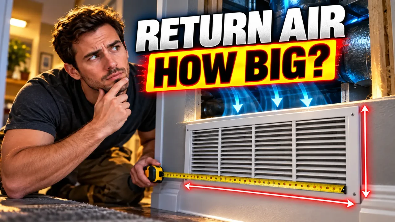
HVAC Return Air Grille Size Calculator
Quick answer: The HVAC Return Air Grille Size Calculator estimates the grille face area needed to carry a specified return-air airflow without exceeding the selected face-velocity target. The core relationship is airflow divided by velocity, with the grille's free-area ratio used to convert required open area into nominal grille area.
TL;DR / Key Takeaways
- Primary Function: Estimate return-air grille size from airflow requirements.
- Key Inputs: Return airflow in CFM, target face velocity, and free-area ratio.
- Core Output: Required free area and estimated gross grille area.
- Best Suited For: Preliminary residential HVAC return-grille sizing and comparison of grille options.
Return air grille sizing is primarily an airflow-area problem. A grille must provide enough effective open area for the required CFM while keeping air velocity within a suitable range for the installation. Higher velocity can allow a smaller grille, but it can also increase pressure loss and audible airflow, particularly where the return is located close to occupants.
How to Use HVAC Return Air Grille Size Calculator?
- Enter the required airflow. Use the return airflow in cubic feet per minute (CFM). For a whole-system return, the design airflow should come from the equipment selection or HVAC design rather than assuming tonnage alone. A commonly used preliminary relationship is approximately 400 CFM per ton, but actual equipment requirements can differ.
- Select the target face velocity. Lower velocity generally requires more grille area. ASHRAE guidance shows that appropriate return-inlet velocity depends on location and acoustic requirements, while residential equipment-selection guidance commonly discusses return grille face velocities in the 400–600 FPM range.
- Account for free area. The nominal grille face is not completely open. Louvers, bars, frames, and filter media reduce the effective area through which air passes. Use the manufacturer's published free-area value when selecting a specific grille.
- Review the calculated size. Compare the required gross area with available standard grille dimensions and consider splitting a large return airflow between multiple grilles when the required single opening is impractical.
What Formula Does the Calculator Use?
The fundamental airflow relationship is:
Required Free Area (ft²) = CFM ÷ Face Velocity (FPM)
When the result is expressed in square inches:
Required Free Area (in²) = CFM × 144 ÷ Face Velocity
To account for the portion of the grille face that is actually open:
Required Gross Grille Area (in²) = CFM × 144 ÷ (Face Velocity × Free-Area Ratio)
- CFM = required return airflow in cubic feet per minute.
- Face Velocity = airflow velocity through the grille's effective opening, in feet per minute.
- Free-Area Ratio = effective open area divided by total grille face area.
- 144 = square-inch conversion factor from square feet.
For example, suppose a return needs to handle 800 CFM at a 400 FPM target with a 70% free-area ratio. The required free area is 800 × 144 ÷ 400 = 288 square inches. Dividing 288 by 0.70 gives approximately 411 square inches of gross grille face area. A nominal grille selected for the installation should therefore provide at least that much area, subject to the manufacturer's actual performance data.
Return Air Grille Sizing Reference
| Design Item | Relationship | Why It Matters |
|---|---|---|
| Return airflow | CFM | Defines how much air the grille must carry. |
| Required free area | CFM × 144 ÷ FPM | Represents the effective open area available to airflow. |
| Free-area ratio | Free area ÷ gross area | Accounts for louvers, bars, frames, or filter media. |
| Gross grille area | Free area ÷ free-area ratio | Approximates the physical face area needed. |
| Multiple returns | Total CFM ÷ number of grilles | Distributes airflow when one grille would be excessively large. |
As a preliminary reference, ASHRAE's small forced-air heating and cooling guidance describes return grilles as commonly selected around 400–600 FPM at the face and notes that filter grilles should use a substantially lower velocity, with 300 FPM identified for filter-grille applications. ASHRAE also emphasizes that grille selection should ultimately be based on the performance data for the selected grille rather than a rule of thumb alone.
Filter Grilles vs. Plain Return Grilles
A filter grille needs additional attention because the filter adds resistance to the return path. The effective airflow area is therefore influenced by both the grille construction and the filter assembly. A filter-grille design should not automatically be sized using the same assumptions as an open return grille.
The manufacturer's published free-area and airflow-pressure-drop data should take priority when a specific grille or filter grille has already been selected. A generic percentage is useful for preliminary estimation, but it is not a substitute for the product's actual performance data.
Technical Edge Cases and Limitations
- Known equipment airflow: Use the equipment's required design airflow when available rather than estimating CFM solely from nominal tonnage.
- Filter returns: Account for the filter's airflow resistance and use the filter grille manufacturer's performance information.
- Small grilles: Free-area ratios can vary substantially with grille construction and dimensions, so a generic ratio may become less representative.
- Large airflow: If one grille becomes impractically large, distributing the airflow across multiple return grilles can provide more installation flexibility.
- Acoustic requirements: The acceptable velocity depends on grille location, occupancy, acoustical requirements, and grille construction.
- Full HVAC design: Grille area alone does not size the complete return-air system. Duct dimensions, fittings, filter pressure drop, static pressure, equipment requirements, and room-to-room return paths also matter.
Technical Disclaimer: This calculator provides a preliminary grille-area estimate from airflow and face-velocity assumptions. Final grille selection should be checked against the selected manufacturer's free-area and performance data and the applicable HVAC design requirements.
Technical references: The methodology is consistent with the airflow-area relationship used for grille selection and with guidance published by ASHRAE and the Air Conditioning Contractors of America (ACCA), including Manual D material concerning residential return-air design.
Author: Michael R. Lawson, HVAC Design Engineer
Author Description: HVAC design professional focused on residential air distribution, return-air sizing, duct-system fundamentals, and practical equipment application.
Technical Review: Reviewed for consistency with standard airflow-area calculations, return-inlet velocity considerations, free-area effects, and the distinction between preliminary grille sizing and complete HVAC system design.
