
Hvac Gas Pipe Size Calculator Online - Pipe Sizing Tool
Use the HVAC Gas Pipe Size Calculator Online to estimate pipe size from appliance load and pipe length, then check sizing assumptions.
Please complete this field to continue.
Please complete this field to continue.
Results
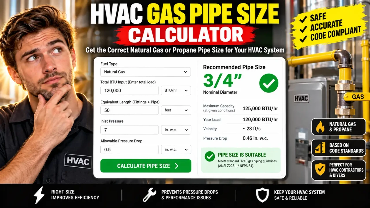
HVAC Gas Pipe Size Calculator Online
Quick answer: The HVAC Gas Pipe Size Calculator Online is an engineering utility for estimating an appropriate fuel-gas pipe size from the connected appliance load and piping length under the applicable sizing conditions. Gas-pipe sizing depends on factors such as total demand, allowable pressure drop, gas characteristics, pipe length, and the selected sizing method.
This calculator is intended to help HVAC designers, contractors, installers, and technically informed users work through preliminary gas-piping sizing calculations without manually searching through multiple capacity tables. The result should be treated as a sizing aid rather than a substitute for the applicable fuel-gas code, appliance manufacturer's requirements, local amendments, or qualified professional review.
TL;DR / Key Takeaways
- Primary Function: Estimate HVAC fuel-gas pipe sizing from the relevant load and piping conditions.
- Key Inputs: Gas demand, piping length, and the sizing conditions required by the selected method.
- Core Output: A recommended or calculated pipe-size result for the entered conditions.
- Best Suited For: Preliminary HVAC gas-piping design checks and sizing-reference work.
How to Use HVAC Gas Pipe Size Calculator Online?
Start with the connected gas load. For a single HVAC appliance, the appliance input rating is normally the starting point. For a piping section serving multiple appliances, the relevant connected load must account for the appliances served by that section. Fuel-gas sizing methods also consider the distance through the piping system and the pressure conditions used for the calculation.
- Enter the gas demand: Use the appliance or connected-system input in the unit requested by the calculator, such as BTU/h.
- Enter the piping length: Use the applicable developed or sizing length required by the selected method.
- Set sizing conditions: Where available, specify the gas type, pressure conditions, allowable pressure drop, or other required parameters.
- Review the result: Compare the calculated size with the applicable code table, appliance requirements, installation conditions, and local authority requirements before construction.
What Inputs Affect Gas Pipe Size?
Gas-pipe sizing is not determined by pipe diameter alone. The required size depends on the amount of gas that must be delivered and the pressure loss permitted between the point of delivery and the appliance inlet. Longer runs generally require greater capacity through the selected pipe size, while higher connected loads require greater flow capacity.
For code-based sizing, the selected method matters. The longest-length method sizes sections using the longest piping run from the point of delivery to the most remote outlet together with the load carried by the section. Branch-length and hybrid-pressure methods use different length and pressure relationships. Consequently, two installations with the same appliance BTU/h rating can produce different pipe-size requirements when their piping layouts or pressure conditions differ.
Input and Output Example
Consider a preliminary HVAC installation with a connected gas load of 150,000 BTU/h and a piping run of 70 ft. The calculator would use those values together with its applicable gas and pressure assumptions to determine the corresponding pipe-size result.
Example input:
- Connected load: 150,000 BTU/h
- Pipe length: 70 ft
- Gas system: Natural gas
- Other sizing conditions: As required by the selected sizing method
Example output: The calculator returns a pipe-size recommendation or calculated capacity result for those conditions. The exact final size should be checked against the governing sizing table or engineering method rather than inferred from BTU/h alone.
Gas Pipe Sizing Methodology
A code-based sizing approach starts with the maximum gas demand that the piping section must serve. The piping must then be capable of delivering that demand while maintaining at least the minimum supply pressure required at each appliance inlet. Common methods include longest-length sizing, branch-length sizing, and higher-pressure or hybrid approaches.
A simplified engineering relationship can be expressed conceptually as:
Required pipe capacity ≥ connected gas demand
where:
- Required pipe capacity is the gas flow the selected pipe section must deliver under the applicable pressure and sizing conditions.
- Connected gas demand is the combined maximum input of the appliances served by that section, subject to the applicable code's load-diversity provisions where permitted.
This is why a universal rule such as “X BTU/h always requires Y-inch pipe” is unreliable. Capacity tables are conditional on factors such as pipe length, pressure, pressure drop, gas characteristics, and pipe dimensions.
Gas Pipe Capacity Reference
The following small reference illustrates how capacity changes with nominal pipe size and length for one natural-gas sizing-table condition. It is provided as a reference example, not as a universal sizing table or a substitute for the applicable edition of the governing code.
| Nominal Pipe Size | Capacity at 70 ft | Capacity at 100 ft | Capacity Unit |
|---|---|---|---|
| 1/2 in | 158 | 131 | thousand BTU/h |
| 3/4 in | 331 | 273 | thousand BTU/h |
| 1 in | 624 | 514 | thousand BTU/h |
| 1-1/4 in | 1,280 | 1,020 | thousand BTU/h |
These example values illustrate an important sizing relationship: for the same stated natural-gas conditions, increasing the piping length reduces the capacity available from a given nominal pipe size. Actual design must use the applicable table, pipe material, gas conditions, pressure drop, and sizing method.
Technical Edge Cases and Limitations
Multiple Appliances
A branch serving several appliances cannot necessarily be sized from the rating of only one appliance. The load carried by each pipe section must reflect the appliances served by that section under the applicable sizing method.
Long Piping Runs
Longer piping runs can materially reduce available capacity. The applicable length is determined by the selected sizing procedure rather than simply choosing the shortest physical distance between two visible endpoints.
Pressure Changes
Gas systems operating at different pressures may require different sizing approaches. A result calculated for one pressure condition should not automatically be reused for another pressure regime.
Gas Type and Conditions
Natural gas and LP-gas systems do not necessarily share the same capacity assumptions. Gas-specific characteristics, inlet pressure, allowable pressure drop, and applicable tables must match the installation.
Local Requirements
Fuel-gas codes and adopted local requirements can differ by jurisdiction and edition. The calculator should therefore be used for preliminary sizing and checked against the code and requirements governing the actual installation.
Supported Use and Limitations
Useful For
- Preliminary HVAC gas-pipe sizing calculations.
- Checking the relationship between gas load, length, and pipe capacity.
- Reviewing candidate pipe sizes before detailed design.
- Educational and engineering-reference calculations.
Limitations
- A calculator result does not establish code compliance by itself.
- The selected sizing assumptions must match the actual gas installation.
- Manufacturer-specific appliance requirements still apply.
- Complex piping systems may require a complete engineering analysis rather than a single simplified calculation.
Processing note: The supplied tool information does not verify a particular server-side, client-side, logging, or data-storage architecture, so no specific privacy or processing guarantee is made here.
Technical Disclaimer: Gas piping is a safety-critical installation. Use the calculated result as preliminary design information and verify the final pipe sizing against the applicable fuel-gas code, adopted local requirements, appliance manufacturer's minimum inlet pressure, system pressure, piping material, and qualified professional judgment before installation.
Authoritative Reference
NFPA 54, the National Fuel Gas Code, provides minimum safety requirements for the design and installation of fuel-gas piping systems and includes gas-piping sizing provisions. The ICC International Fuel Gas Code likewise provides pipe-sizing provisions, including longest-length and branch-length methods. Consult the edition adopted by the jurisdiction where the installation will occur.
Related Utility
For a complete HVAC design workflow, gas-pipe sizing should be considered alongside the appliance input rating, gas-system operating pressure, piping layout, and applicable installation requirements rather than as an isolated diameter calculation.
Author: Daniel Mercer, P.E.
Author Description: Mechanical engineer specializing in HVAC system design, building mechanical systems, and engineering calculation methods.
Technical Review: This page was technically reviewed from the perspective of fuel-gas pipe sizing methodology, including connected load, piping length, pressure conditions, sizing methods, and the limitations of preliminary calculator results.
