
Voltage Standing Wave Ratio Calculator Tool Online
Calculate voltage standing wave ratio from reflection coefficient values. Understand VSWR, impedance matching, reflected power, and RF transmission line performance.
Please complete this field to continue.
Please complete this field to continue.
Results
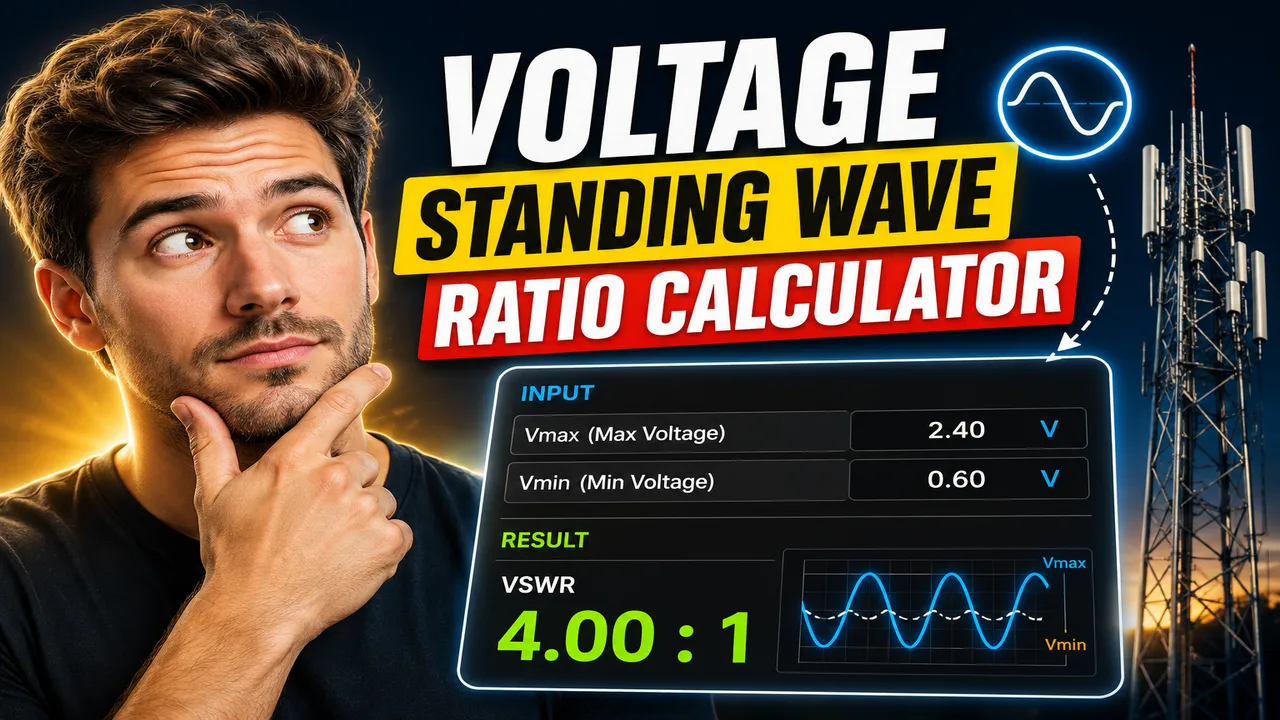
Voltage Standing Wave Ratio Calculator Tool Online
Quick answer: The Voltage Standing Wave Ratio (VSWR) Calculator is an electrical engineering calculator that determines the ratio of maximum to minimum voltage on a transmission line. Given the magnitude of the reflection coefficient, it calculates VSWR, a key indicator of impedance matching between a transmission line and its load.
The Voltage Standing Wave Ratio Calculator Tool Online helps radio-frequency (RF) engineers, antenna technicians, electronics students, and communications professionals evaluate transmission-line matching. VSWR describes how much voltage variation occurs along a line when incident and reflected waves combine. A lower VSWR indicates a better match, while a higher value indicates greater reflection.
VSWR is particularly useful when checking antennas, coaxial cables, RF connectors, transmitters, and other components in radio-frequency systems. However, VSWR alone does not identify the physical cause of a mismatch. Connector faults, antenna tuning, cable characteristics, and load impedance can all influence the measured result.
Key Takeaways
- Primary function: Calculate the voltage standing wave ratio from a reflection coefficient.
- Core relationship: VSWR increases as the magnitude of the reflection coefficient approaches 1.
- Common applications: Antenna matching, RF transmission lines, and impedance analysis.
- Important distinction: VSWR describes mismatch severity, not the exact location or cause of a fault.
How to Use Voltage Standing Wave Ratio Calculator Tool Online?
- Enter the reflection coefficient: Supply the magnitude of the voltage reflection coefficient, usually represented by the Greek letter rho (ρ). Its valid magnitude is between 0 and 1.
- Calculate the ratio: Apply the VSWR relationship to determine the standing-wave voltage ratio.
- Interpret the result: Compare the calculated value with the matching requirements of the RF system or antenna installation.
- Verify the measurement: If working with real equipment, compare the calculation with a suitable SWR meter, directional coupler, or vector network analyzer measurement.
The supplied tool name does not establish its actual interface fields, supported input modes, or displayed output fields. The following technical explanation describes the standard VSWR calculation and should be aligned with the calculator's implemented controls before publication.
What Is Voltage Standing Wave Ratio (VSWR)?
Voltage Standing Wave Ratio is the ratio of the maximum voltage amplitude to the minimum voltage amplitude along a transmission line:
VSWR = Vmax / Vmin
Here, Vmax is the maximum voltage amplitude and Vmin is the minimum voltage amplitude created by the interference of incident and reflected waves. VSWR is a dimensionless ratio and is conventionally expressed as a ratio such as 1:1, 1.5:1, or 3:1.
The reflection coefficient describes the amplitude and phase relationship between reflected and incident voltage waves. For VSWR calculations, the magnitude of the voltage reflection coefficient is used:
VSWR = (1 + |Γ|) / (1 - |Γ|)
In this formula, Γ is the complex voltage reflection coefficient, and |Γ| is its magnitude. For a passive load connected to a transmission line under the usual steady-state assumptions, the magnitude ranges from 0 to 1. A magnitude of 0 represents no reflected wave, while a magnitude of 1 represents total reflection.
Input and Output Example
Consider an RF transmission line with a reflection coefficient magnitude of 0.2.
Input:
- Voltage reflection coefficient magnitude: |Γ| = 0.2
Calculation:
VSWR = (1 + 0.2) / (1 - 0.2)
VSWR = 1.2 / 0.8 = 1.5
Result: VSWR = 1.5:1.
This result indicates that the maximum voltage amplitude is 1.5 times the minimum voltage amplitude along the line. It does not, by itself, establish whether the connected antenna or load meets a particular application's performance requirements.
VSWR Formula and Variable Definitions
The standard relationship between reflection coefficient magnitude and VSWR is:
S = (1 + r) / (1 - r)
- S: Voltage standing wave ratio.
- r: Magnitude of the voltage reflection coefficient, |Γ|.
- 1 + r: Sum used to determine the normalized maximum voltage amplitude.
- 1 - r: Difference used to determine the normalized minimum voltage amplitude.
The equation is valid for 0 ≤ r < 1. At r = 0, VSWR equals 1. At r = 1, the denominator becomes zero and the VSWR tends toward infinity, representing total reflection in the idealized model.
VSWR Reference Table
The following values provide a quick reference for interpreting common reflection coefficient magnitudes. They are mathematical examples, not universal pass/fail limits for every RF system.
| Reflection Coefficient Magnitude |Γ| | VSWR | Reflected Power Fraction | Interpretation |
|---|---|---|---|
| 0.00 | 1.00:1 | 0% | Ideal match |
| 0.10 | 1.22:1 | 1% | Low reflection |
| 0.20 | 1.50:1 | 4% | Moderate mismatch |
| 0.30 | 1.86:1 | 9% | Greater mismatch |
| 0.50 | 3.00:1 | 25% | Significant mismatch |
| 0.75 | 7.00:1 | 56.25% | High reflection |
| 0.90 | 19.00:1 | 81% | Very high reflection |
| 1.00 | Infinite in the ideal limit | 100% | Total reflection |
The reflected power fraction in this table is calculated as |Γ|² for a single traveling wave on a compatible reference impedance. A reflected power percentage should not be confused with a percentage of voltage reflection: power depends on the square of the reflection coefficient magnitude.
How Does the VSWR Calculation Work?
The calculation converts the reflection coefficient magnitude into a ratio of voltage maxima and minima. The relationship follows from the constructive and destructive interference of incident and reflected waves on a transmission line.
- Determine the magnitude of the voltage reflection coefficient.
- Add the magnitude to 1 to calculate the normalized maximum-voltage factor.
- Subtract the magnitude from 1 to calculate the normalized minimum-voltage factor.
- Divide the first factor by the second to obtain VSWR.
If a tool instead accepts return loss in decibels, the corresponding reflection coefficient magnitude can be obtained using:
|Γ| = 10(-RL/20)
where RL is the positive return-loss value in decibels. VSWR can then be calculated using the standard equation. This is an alternative mathematical input method, not a claim that the supplied calculator currently supports return-loss input.
VSWR, Return Loss, and Reflection Coefficient
These three quantities describe related aspects of transmission-line mismatch, but they are not interchangeable.
| Quantity | Definition | Unit |
|---|---|---|
| VSWR | Maximum voltage divided by minimum voltage | Dimensionless ratio |
| Reflection coefficient magnitude | Reflected voltage-wave amplitude divided by incident voltage-wave amplitude | Dimensionless ratio |
| Return loss | -20 log10(|Γ|) | Decibels (dB) |
| Reflected power fraction | |Γ|² | Fraction or percentage |
A larger positive return loss generally corresponds to a smaller reflection coefficient magnitude and a lower VSWR. These relationships assume compatible reference conditions and the standard definition of return loss.
Edge Cases and Limitations
- Perfect match: A reflection coefficient magnitude of zero produces VSWR = 1:1.
- Total reflection: A magnitude of one makes the denominator zero, so the idealized VSWR is infinite rather than a finite number.
- Invalid magnitude: Negative magnitudes and values greater than one are outside the ordinary input range for this calculation.
- Rounding: Displayed values may be rounded; use sufficient precision for engineering calculations.
- Measurement uncertainty: Instrument calibration, connector condition, frequency, and measurement setup can affect real-world readings.
- No fault localization: VSWR alone cannot identify the location of a mismatch or determine which component is responsible.
For practical RF work, calculate or measure VSWR at the frequency and reference plane relevant to the system. A load's mismatch may vary with frequency, so one value should not be assumed to describe an entire operating band.
Technical References
- Keysight Technologies — Vector Network Analyzer Measurement Basics
- Analog Devices — Understanding Return Loss and VSWR
Technical Disclaimer: This calculator's mathematical result should be checked against the actual RF system, operating frequency, impedance reference, instrument accuracy, and equipment specifications before making installation or transmission decisions.
Author: Daniel Mercer
Author Description: Electrical engineering writer focused on radio-frequency systems, transmission lines, and antenna measurement principles.
Technical Review: The VSWR formula, reflection-coefficient relationship, return-loss conversion, and ideal boundary cases should be checked against established RF engineering references before this content is published as a description of the live calculator.
