
Solar Panel Inter-Row Spacing Calculator Explained
Learn how solar panel inter-row spacing relates to panel dimensions, tilt, and solar elevation. Review shadow geometry and plan PV layouts with informed spacing assumptions.
Please complete this field to continue.
Please complete this field to continue.
Please complete this field to continue.
Results
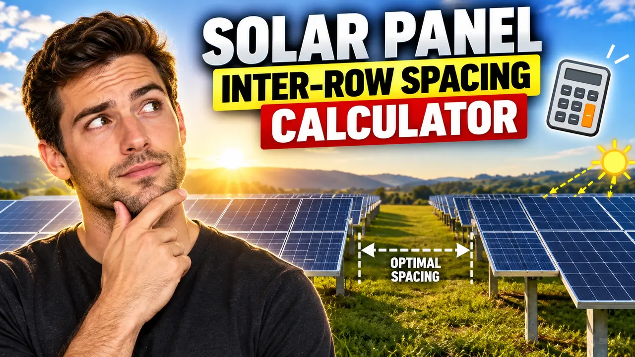
Solar Panel Inter-Row Spacing Calculator
The Solar Panel Inter-Row Spacing Calculator is an engineering calculator designed to estimate the minimum distance between adjacent rows of solar panels to reduce shading from one row onto the next. It is intended for solar PV designers, installers, engineers, and site planners evaluating ground-mounted or other row-arranged photovoltaic systems.
Quick answer: Solar panel inter-row spacing is the horizontal distance between adjacent panel rows. A preliminary spacing estimate can be calculated from panel dimensions, tilt angle, solar elevation angle, and an acceptable shading criterion. The appropriate distance depends on the site's latitude, the design time and date, terrain, and the project's energy-production objectives.
Important implementation note: The supplied tool name and Open Graph image identify the calculator, but do not specify its actual input fields, calculation algorithm, or output units. The methodology below is a transparent engineering reference, not a claim that the live calculator implements every described parameter or formula. Confirm the calculator's actual fields and results against its implementation before publishing this content as a description of its exact behavior.
TL;DR / Key Takeaways
- Primary Function: Estimate the spacing needed between neighboring solar panel rows to manage inter-row shading.
- Key Variables: Panel geometry, tilt, solar elevation, and the selected shading design condition.
- Core Output: A spacing distance, typically expressed in metres or feet when those units are supported.
- Best Suited For: Preliminary PV layout planning and comparison of row-spacing scenarios.
Why Does Inter-Row Spacing Matter?
Solar modules mounted in rows can shade the modules behind them when the sun is low in the sky. This is especially important in the morning, afternoon, and winter months, when the solar elevation angle decreases and shadows become longer. If rows are placed too close together, the front row can reduce the irradiance received by the next row.
Increasing the distance between rows generally reduces direct inter-row shading, but it also increases the land area required for a given installed capacity. A useful layout balances shading losses, available site area, access paths, maintenance requirements, and the project's energy-yield target.
Inter-row spacing is not the same as the physical gap between modules in a single row. It describes the layout distance between neighboring rows, which may be measured from corresponding points on the modules or from the front edge of one row to the rear edge of the next. The reference points must be defined consistently when comparing calculated and measured distances.
How to Use Solar Panel Inter-Row Spacing Calculator?
- Identify the panel geometry. Determine the dimension of the module or tilted panel plane in the direction of the slope. This is often the module's length along the tilt direction, not its width along the row.
- Determine the tilt angle. Use the angle between the panel plane and the horizontal ground. A steeper tilt generally increases the vertical height difference across the panel plane.
- Select the shading design condition. Decide the solar elevation and time window that the layout should accommodate. A winter-solstice condition is commonly considered for conservative seasonal design, but the appropriate criterion depends on project requirements.
- Enter supported values and calculate. If the live tool provides these fields, enter the required dimensions, angles, and units, run the calculation, and check the returned spacing against the site's layout constraints.
Use the actual labels and units shown by the interactive calculator. Do not enter a solar azimuth angle where the calculator expects solar elevation, or a module's across-row width where it expects the dimension along the tilted plane.
Input and Output Example
The following worked example demonstrates a common geometric approach to estimating row spacing. It is illustrative and is not a verified output from the live calculator.
Example inputs
- Panel-plane length in the tilt direction: 2.0 m
- Panel tilt from horizontal: 25°
- Design solar elevation angle: 20°
- Assumed ground: level
- Assumed shadow direction: perpendicular to the row
Step 1: Calculate the vertical height
For a panel of sloped length L tilted at angle β, the vertical rise is:
H = L × sin(β)
Using the example values:
H = 2.0 × sin(25°) ≈ 0.845 m
Step 2: Estimate the horizontal shadow length
For a solar elevation angle α, a simplified horizontal shadow length is:
S = H ÷ tan(α)
S = 0.845 ÷ tan(20°) ≈ 2.32 m
This means the vertical height difference of 0.845 m produces an approximately 2.32 m horizontal shadow component under the assumed solar elevation and shadow geometry.
Step 3: Interpret the result
The 2.32 m result is a simplified shadow-length component, not automatically the final row pitch or clear gap. The required spacing depends on the row reference points, panel orientation, whether a no-shading or limited-shading criterion is used, and the relationship between the shadow and the next row.
For example, a calculator might report centre-to-centre row pitch, while a site drawing specifies the clear ground distance between panel edges. Those measurements are not interchangeable. Confirm the definition of the output before using it in a construction layout.
Solar Panel Inter-Row Spacing Formula and Methodology
For a simplified two-dimensional layout with level ground, a straight tilted panel plane, and the shadow projected in the cross-row direction, the vertical component of the panel geometry can be calculated using trigonometry.
Vertical rise:
H = L sin(β)
Horizontal shadow component:
S = H / tan(α) = L sin(β) / tan(α)
Where:
- L = panel-plane length in the tilt direction, in metres or feet.
- β = panel tilt angle measured from horizontal.
- H = vertical rise across the tilted panel plane, in the same length unit as L.
- α = solar elevation angle measured above the horizon.
- S = simplified horizontal shadow component, in the same length unit as L.
Angles must be interpreted consistently. If a calculator accepts degrees, enter the tilt and solar elevation in degrees. Length units must also be consistent; using metres for the panel length produces metres for the calculated shadow component.
This relationship describes a geometric shadow component. It does not by itself establish the final spacing rule for every mounting configuration. A full layout calculation may need to account for the lower and upper edges of the panels, row pitch, solar azimuth, row orientation, terrain slope, tracking movement, and the selected acceptable-shading window.
Inter-Row Spacing Reference Table
The table below illustrates how solar elevation affects the shadow component for a fixed vertical rise of 0.845 m, as calculated in the worked example. The values are rounded to two decimal places and are geometric estimates, not universal spacing recommendations.
| Solar Elevation | Vertical Rise | Estimated Shadow Component | Interpretation |
|---|---|---|---|
| 10° | 0.845 m | 4.79 m | Very low sun; long shadow |
| 15° | 0.845 m | 3.15 m | Low sun; longer shadow |
| 20° | 0.845 m | 2.32 m | Example design condition |
| 30° | 0.845 m | 1.46 m | Higher sun; shorter shadow |
| 45° | 0.845 m | 0.85 m | High sun; shadow equals height |
The relationship is nonlinear. As the solar elevation approaches the horizon, the tangent of the elevation angle approaches zero, and the theoretical shadow length becomes very large. At a solar elevation of zero degrees, this simplified equation is undefined. Such low-angle conditions should not be handled by treating the result as a practical finite spacing recommendation.
Factors That Change the Required Row Spacing
- Panel tilt: Increasing the tilt generally increases the vertical rise for the same panel-plane length, which can lengthen the shadow.
- Solar elevation: Lower solar elevation produces longer shadows. The design angle should reflect the site's latitude, date, time, and chosen shading criterion.
- Row orientation: The component of a shadow that falls across adjacent rows depends on the sun's azimuth relative to the row direction.
- Terrain slope: Uneven ground changes the relative elevation of neighboring rows and can invalidate a level-ground estimate.
- Tracking systems: Single-axis and dual-axis trackers change module orientation over time, so fixed-tilt geometry may not describe their full operating envelope.
- Land-use constraints: Walkways, equipment clearance, drainage, fire access, and maintenance routes can require spacing beyond a simple shading calculation.
Technical Edge Cases and Limitations
- Solar elevation at or below zero: The simplified equation is undefined at zero elevation and does not represent useful daylight shading conditions below the horizon.
- Zero panel length or zero tilt: These inputs produce a zero vertical rise in the simplified geometry, but a zero result should not be interpreted as a complete PV layout recommendation.
- Unit mismatch: Mixing metres and feet without conversion produces inconsistent dimensions.
- Unspecified output reference: A shadow length, clear gap, and centre-to-centre row pitch represent different quantities.
- Non-level ground: Sloped or irregular terrain requires a more detailed geometric assessment.
- Three-dimensional shadows: The simplified formula does not fully account for solar azimuth or shadows that fall partly along the row.
- Partial shading: A no-shading criterion differs from a design that permits limited shading during selected hours.
The calculator should be used only for the inputs and conditions it actually supports. Since its live implementation and field validation rules were not supplied, no particular error message, unit selector, supported mounting system, or automated solar-position feature can be confirmed here.
Engineering Considerations and Technical Disclaimer
Use a preliminary spacing estimate to compare layout alternatives, not as the sole basis for final construction drawings. Before finalizing a PV array, validate the row geometry using site coordinates, the relevant solar-position conditions, the mounting structure's dimensions, terrain surveys, and project-specific shading requirements.
Where shading affects the design, evaluate the selected time window rather than relying on one arbitrary solar elevation. A layout designed for a low winter sun may require substantially more land than one designed to limit shading only around midday. The appropriate trade-off depends on energy yield, land cost, installed capacity, and project constraints.
Technical Disclaimer: This calculator is intended for preliminary engineering estimates. The simplified equations and example values on this page do not replace a site-specific shading study, structural assessment, electrical design, or applicable local requirements. Confirm final row spacing with a qualified solar PV designer or engineer.
Author
Author Name: Michael Turner
Author Description: Electrical Engineering Content Specialist focused on photovoltaic system geometry, solar array layout principles, and practical engineering calculations.
Technical Review: This page's stated trigonometric relationships and worked example should be checked against the live calculator's actual implementation before being treated as a verified description of its outputs.
