
Solar Panel Series Vs Parallel Calculator Online Explained
Compare solar panel series and parallel wiring with panel voltage, current, and quantity to estimate array output and review key electrical design limits before installation.
Please complete this field to continue.
Please complete this field to continue.
Please complete this field to continue.
Please complete this field to continue.
Please complete this field to continue.
Results
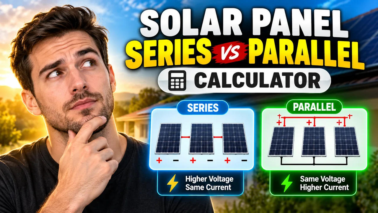
Solar Panel Series Vs Parallel Calculator Online
Quick answer: The Solar Panel Series Vs Parallel Calculator Online is an electrical calculator concept for comparing solar panel wiring configurations. It uses panel voltage, current, panel quantity, and the selected series or parallel arrangement to estimate the resulting array voltage and current. These calculations help solar installers, off-grid system designers, RV owners, and solar DIY users evaluate wiring options before selecting a charge controller or inverter.
Choosing between series and parallel solar panel wiring changes the electrical characteristics of a photovoltaic (PV) array. Series wiring increases voltage while keeping current approximately the same. Parallel wiring increases current while keeping voltage approximately the same. The correct configuration depends on the solar panel specifications, equipment input limits, cable design, shading conditions, and the operating requirements of the solar power system.
This page is intended to explain the calculation logic and help users compare common wiring configurations. The exact fields, supported options, rounding behavior, and output features of the live calculator should be confirmed against its implementation.
How to Use Solar Panel Series Vs Parallel Calculator Online?
- Enter the panel voltage. Use the voltage value from the panel datasheet. For basic calculations, distinguish maximum power voltage (Vmp) from open-circuit voltage (Voc).
- Enter the panel current. Use maximum power current (Imp) for operating-point power estimates or short-circuit current (Isc) when evaluating current-related design limits.
- Specify the number of panels. Use the number of electrically identical panels in the proposed string or parallel group.
- Compare configurations. Calculate the theoretical array voltage, current, and power for series and parallel arrangements, then verify the result against the equipment ratings.
Series vs Parallel Solar Panel Wiring
In a series-connected string, the positive terminal of one panel connects to the negative terminal of the next. The voltages add, while the same current flows through each panel in the string. In a parallel-connected group, positive terminals are connected together and negative terminals are connected together. The currents add, while the voltage remains approximately equal to the voltage of one panel.
| Electrical characteristic | Series connection | Parallel connection |
|---|---|---|
| Total voltage | Sum of panel voltages | Approximately one panel's voltage |
| Total current | Approximately one panel's current | Sum of panel currents |
| Total power, ideally | Sum of panel power | Sum of panel power |
| Typical design consideration | Maximum PV input voltage and cold-weather Voc | Combined current, cable sizing, fuses, and combiner ratings |
| Partial shading | Can reduce string current and energy production | May reduce the impact on other parallel branches, depending on system design |
Solar Panel Series and Parallel Formulas
For a simplified array made from identical panels operating under the same conditions, let:
- N = number of panels in the group
- Vmp = voltage at maximum power, in volts
- Imp = current at maximum power, in amperes
- Pmp = power at maximum power, in watts
Series connection formula
Array voltage: Varray = N × Vmp
Array current: Iarray ≈ Imp
Array power: Parray ≈ N × Vmp × Imp
Parallel connection formula
Array voltage: Varray ≈ Vmp
Array current: Iarray = N × Imp
Array power: Parray ≈ Vmp × N × Imp
These equations are idealized calculations. Actual operating voltage and current depend on irradiance, cell temperature, shading, mismatch between modules, wiring losses, and the maximum power point tracking (MPPT) behavior of the controller or inverter.
Worked Example: Four 400 W Solar Panels
Assume four identical panels, each with a maximum power voltage of 40 V and a maximum power current of 10 A.
| Input or result | Series configuration | Parallel configuration |
|---|---|---|
| Panel quantity | 4 | 4 |
| Voltage per panel | 40 V | 40 V |
| Current per panel | 10 A | 10 A |
| Array voltage at maximum power | 160 V | 40 V |
| Array current at maximum power | 10 A | 40 A |
| Theoretical array power | 1,600 W | 1,600 W |
The example demonstrates that ideal series and parallel configurations can produce the same combined rated power while having substantially different voltage and current. Higher voltage can reduce current for a given power and help reduce cable losses, but it also increases the importance of maximum PV voltage limits. Parallel wiring keeps voltage lower but requires the wiring and protection equipment to accommodate greater combined current.
Technical Reference: When to Choose Series or Parallel
| Design condition | What series wiring changes | What parallel wiring changes |
|---|---|---|
| Long cable run | Higher voltage and lower current for equivalent power can reduce resistive losses for a suitably designed cable | Higher current can increase voltage drop and resistive losses unless conductors are sized accordingly |
| Controller voltage limit | String Voc increases with panel count and must remain within the controller's permitted PV voltage | Voltage is approximately that of one panel, but the controller's input-current limit remains important |
| Cold weather | Voc typically rises as module temperature falls, so the cold-corrected string voltage must be checked | Cold-weather voltage still matters, although the number of parallel panels does not ideally multiply voltage |
| Shading | One shaded panel can constrain string output, depending on bypass diodes and operating conditions | Separate branches can behave more independently, but shared equipment and mismatch can still reduce output |
| Protection equipment | String voltage ratings, disconnects, and DC arc hazards require attention | Combined branch current, overcurrent protection, and combiner equipment require attention |
How the Calculation Works
The basic calculation multiplies voltage by current to estimate electrical power: P = V × I. For N identical panels connected in series, the ideal array voltage is N times the individual panel voltage, and array current remains approximately the panel current. For N identical panels in parallel, the ideal array current is N times the individual panel current, and array voltage remains approximately the panel voltage.
For panels with different electrical ratings, these simplified formulas are not sufficient to predict actual system performance. Mixed-module arrays can experience mismatch losses, and series strings may be constrained by the lowest-current module under particular operating conditions. Design calculations should use compatible module specifications and the equipment manufacturer's wiring requirements.
Technical Edge Cases and Limitations
- Using Voc instead of Vmp: Voc is useful for maximum-voltage checks, not as a substitute for operating voltage in a normal power calculation.
- Using Isc instead of Imp: Isc is a short-circuit rating and should not be treated as the expected operating current at maximum power.
- Mixed panel ratings: Different panel voltages or currents can create mismatch and prevent simple multiplication from predicting actual output.
- Cold temperatures: Calculate the maximum possible string Voc using the module's temperature coefficient and the expected minimum cell temperature.
- Shading and orientation: Different sunlight levels, tilt angles, or shading patterns can change the operating point and available power.
- Controller compatibility: Check both the maximum PV input voltage and the permissible operating-current or short-circuit-current limits.
- Rounding: Retain adequate precision for design checks. Do not round a voltage value down to make an otherwise incompatible string appear acceptable.
Technical Disclaimer: The formulas and examples above are preliminary engineering estimates for identical panels under idealized conditions. Before installation, verify cold-corrected open-circuit voltage, current limits, overcurrent protection, conductor ampacity, disconnect ratings, grounding, and applicable electrical codes. Follow the solar module and inverter or charge-controller manufacturers' instructions, and consult a qualified solar electrical professional where necessary.
Author and Technical Review
Author Name: Daniel Brooks
Author Description: Electrical engineering content specialist focused on photovoltaic system fundamentals, DC circuit calculations, and solar equipment compatibility.
Technical Review: The formulas, terminology, worked example, and configuration comparison should be reviewed by a qualified electrical engineer against applicable PV equipment specifications before publication. No claim is made here that the live calculator's implementation has been independently tested.
Authoritative References
