
Hvac Condensate Pipe Size Calculator - Toolhox
Calculate HVAC condensate pipe size from equipment capacity and review minimum diameter ranges for preliminary condensate drain sizing.
Please complete this field to continue.
Please complete this field to continue.
Please complete this field to continue.
Please complete this field to continue.
Results
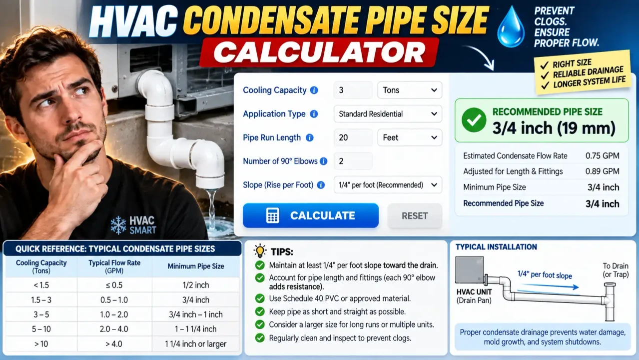
Hvac Condensate Pipe Size Calculator
Quick answer: The Hvac Condensate Pipe Size Calculator helps determine a minimum condensate drain pipe diameter from HVAC equipment capacity and applicable sizing criteria. For code-based sizing, the result should be checked against the governing mechanical/plumbing code and the actual drainage arrangement.
Condensate drain sizing matters because an undersized drain can restrict condensate removal, while an incorrectly designed gravity drain can create drainage or overflow problems. The appropriate pipe size depends on the sizing method being applied, equipment capacity, drainage configuration, slope, and the requirements adopted for the project.
How to Use Hvac Condensate Pipe Size Calculator?
- Enter the equipment capacity: Provide the HVAC cooling capacity in tons of refrigeration as required by the calculator.
- Run the calculation: The calculator evaluates the entered capacity against its condensate-pipe sizing criteria.
- Review the recommended diameter: Use the displayed pipe diameter as the calculator's sizing result, then verify the installation against the applicable project requirements.
What Input Does the Calculator Use?
The primary sizing input is HVAC equipment capacity expressed in tons of refrigeration. One refrigeration ton is approximately 3.517 kW. The capacity is used to identify the applicable pipe-size range in capacity-based sizing tables.
What Does the Result Mean?
The displayed diameter represents the minimum pipe size indicated by the calculator's selected sizing method. It should not automatically be interpreted as a complete condensate-system design. Drain slope, routing, traps, discharge location, combined drains, lifts, pumps, and local requirements can affect the final installation.
Input and Output Example
Example input: HVAC equipment capacity = 18 tons of refrigeration.
Example calculation: 18 tons falls within the “up to 20 tons” capacity range in the referenced IMC condensate drain sizing table.
Example result: The corresponding minimum condensate pipe diameter is 3/4 inch under that table.
| Equipment Capacity | Minimum Condensate Pipe Diameter | Reference Rule |
|---|---|---|
| Up to 20 tons | 3/4 inch | Capacity-based minimum |
| Over 20 to 40 tons | 1 inch | Capacity-based minimum |
| Over 40 to 90 tons | 1-1/4 inch | Capacity-based minimum |
| Over 90 to 125 tons | 1-1/2 inch | Capacity-based minimum |
| Over 125 to 250 tons | 2 inches | Capacity-based minimum |
The International Mechanical Code condensate drain sizing table uses equipment refrigeration capacity to establish these minimum diameters. The table also states the conversion of 1 refrigeration ton to approximately 3.517 kW. Applicable editions and locally adopted provisions should always be checked before construction.
How the Pipe-Size Calculation Works
For the capacity-based method, the basic logic is a range lookup rather than a single universal pipe-flow equation:
Equipment capacity → applicable capacity range → minimum condensate pipe diameter
For example, an input of 35 tons belongs to the “over 20 tons to 40 tons” range, giving a 1-inch minimum diameter under the referenced table. An input of 50 tons belongs to the “over 40 tons to 90 tons” range, giving a 1-1/4-inch minimum diameter.
This approach should not be confused with hydraulic sizing of a gravity condensate line. ASHRAE also publishes condensate-flow capacity information for gravity-flow piping where pipe diameter and line slope are considered. That means a project-specific hydraulic design can require more information than equipment tonnage alone.
Technical Reference and Design Considerations
| Capacity Range | Minimum Diameter | Application Note |
|---|---|---|
| ≤ 20 tons | 3/4 in. | Capacity-based minimum |
| > 20–40 tons | 1 in. | Capacity-based minimum |
| > 40–90 tons | 1-1/4 in. | Capacity-based minimum |
| > 90–125 tons | 1-1/2 in. | Capacity-based minimum |
| > 125–250 tons | 2 in. | Capacity-based minimum |
ASHRAE's pipe-design guidance demonstrates why gravity condensate drainage can require consideration of both pipe diameter and slope. Its gravity-flow tables provide different condensate capacities for different nominal diameters and slopes. Therefore, a capacity-table result should not be treated as a substitute for complete drainage-system design when the installation has unusual routing, long horizontal runs, combined drains, or other hydraulic constraints.
Edge Cases and Limitations
Capacity at a Boundary
Pay attention to whether the entered value falls exactly on a range boundary. “Up to 20 tons” and “over 20 tons to 40 tons” are different ranges, so the calculator should apply the stated boundary definitions rather than treating ranges as approximate.
Very Large Equipment
The referenced capacity table extends through 250 tons. Equipment outside the table's stated range should not be assigned a pipe size by extrapolating the final row without an appropriate engineering or code-based sizing method.
Gravity Drainage
Equipment capacity alone does not describe every hydraulic condition in a gravity condensate system. Pipe slope, drainage configuration, available head, routing, and discharge conditions may affect the required design.
Pumped Condensate
A pumped condensate installation is different from a simple gravity drain. Pump capacity, lift, discharge piping, controls, and manufacturer requirements may govern portions of the system.
Combined Drain Systems
When multiple pieces of equipment discharge into a common drain, the designer should verify the combined drainage arrangement rather than blindly applying the single-equipment result to the entire system.
Code and Professional Review
Condensate disposal requirements can vary by adopted code edition and jurisdiction. The calculator provides a sizing reference, not a complete code-compliance determination.
Technical Disclaimer: This calculator is intended for preliminary condensate pipe-size evaluation. Final HVAC drainage design should be checked against the applicable adopted mechanical/plumbing codes, manufacturer requirements, site conditions, drainage configuration, and qualified professional judgment.
Author and Technical Review
Author: Daniel R. Mercer, P.E. — Mechanical engineer specializing in HVAC systems, building mechanical design, and engineering calculations.
Technical Review: Daniel R. Mercer, P.E. reviews the capacity-based condensate-pipe sizing methodology and its limitations, including the distinction between minimum code-based diameter tables and detailed gravity-flow hydraulic design.
Authoritative references: International Code Council, International Mechanical Code condensate drain sizing provisions; ASHRAE Handbook, Pipe Design guidance for gravity condensate flow.
