
Hvac Return Air Duct Size Calculator By Btu - Free
Calculate HVAC return air duct size from BTU/h using a preliminary airflow and velocity method. Estimate CFM, duct area, and round diameter.
Please complete this field to continue.
Results
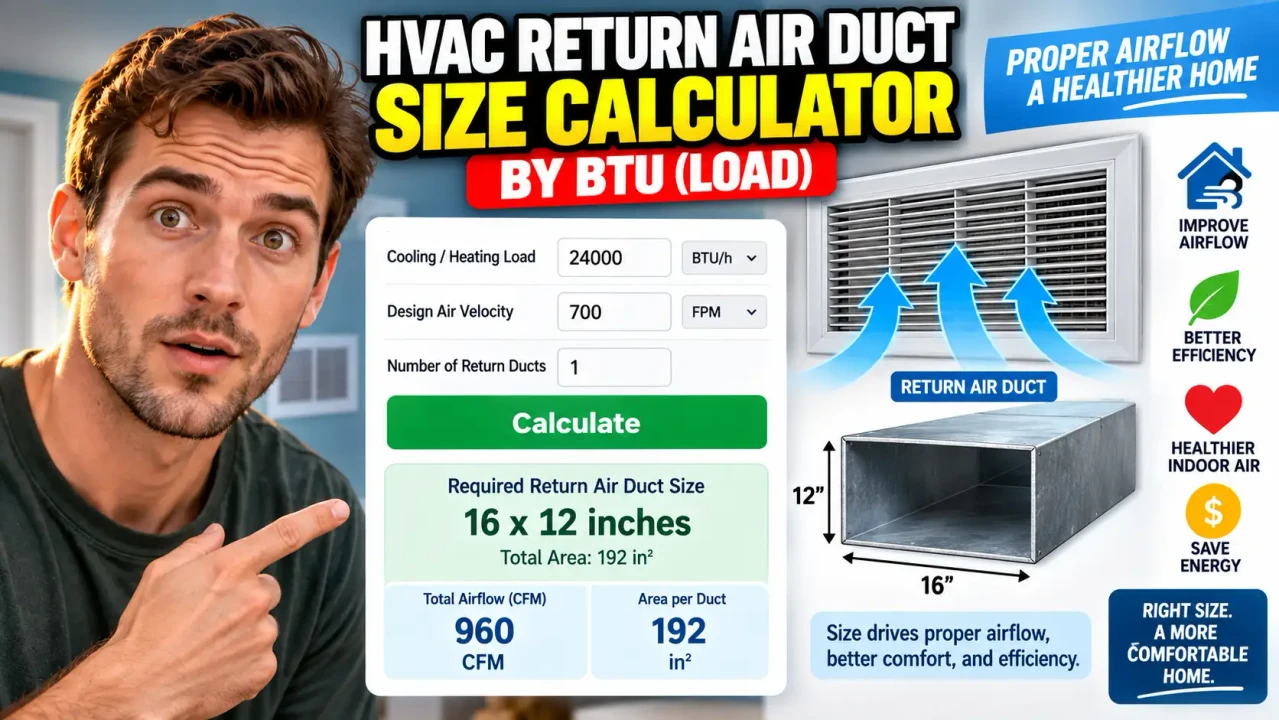
Hvac Return Air Duct Size Calculator By Btu
Quick answer: Hvac Return Air Duct Size Calculator By Btu is a screening calculator that estimates the airflow and return-duct cross-sectional area associated with an HVAC system's BTU/h capacity. It converts BTU/h into a nominal airflow estimate, then uses a target return-air velocity to estimate a suitable duct size.
Return-air sizing is an important part of HVAC duct design because the return path must carry the air delivered by the system back to the air handler. An undersized return can increase air velocity and pressure loss, while an oversized or poorly configured return can create unnecessary material and space requirements. This calculator is intended to provide a practical preliminary estimate from the equipment's nominal BTU/h capacity.
TL;DR / Key Takeaways
- Primary Function: Estimate return-air duct requirements from HVAC capacity in BTU/h.
- Key Input: HVAC heating or cooling capacity in BTU/h.
- Core Method: Convert BTU/h to nominal airflow, then size the return area from airflow and target velocity.
- Best Suited For: Preliminary residential HVAC return-duct sizing and quick design checks.
How to Use Hvac Return Air Duct Size Calculator By Btu?
Start with the nominal HVAC capacity shown on the equipment nameplate or manufacturer documentation. Enter the capacity in BTU/h using the unit expected by the calculator, then calculate the return-air requirement. The result should be treated as a preliminary sizing estimate rather than a complete Manual D duct design.
What should I enter?
Enter the HVAC system capacity in BTU/h. For example, a nominal 36,000 BTU/h system represents a 3-ton class system because 1 refrigeration ton is conventionally associated with 12,000 BTU/h.
What does the calculator estimate?
The BTU/h value is first converted into a nominal airflow estimate. A common preliminary HVAC relationship is approximately 400 CFM per ton, so:
Nominal airflow = (BTU/h ÷ 12,000) × 400
For a 36,000 BTU/h system:
36,000 ÷ 12,000 = 3 tons
3 × 400 = 1,200 CFM
The return-duct area can then be estimated from the airflow and selected design velocity:
Required area (ft²) = CFM ÷ target velocity (FPM)

Required area (in²) = (CFM ÷ target velocity) × 144
Using 600 FPM as an illustrative return-duct velocity:
Required area = 1,200 ÷ 600
              = 2.00 ft²
              = 288 in²
For a circular duct, the equivalent diameter can be calculated from:
D = √(4A ÷ π)
where D is duct diameter and A is the required cross-sectional area in square inches. With 288 in²:
D = √(4 × 288 ÷ π)
  ≈ 19.1 inches
A practical nominal round-duct selection would therefore be approximately 20 inches, subject to the actual airflow, friction rate, fittings, filter resistance, available space, and equipment manufacturer's requirements.
BTU-to-Airflow Reference
| HVAC Capacity | Nominal Tons | Airflow at 400 CFM/Ton | Area at 600 FPM | Equivalent Round Diameter |
|---|---|---|---|---|
| 18,000 BTU/h | 1.5 ton | 600 CFM | 144 in² | 13.5 in |
| 24,000 BTU/h | 2.0 ton | 800 CFM | 192 in² | 15.6 in |
| 30,000 BTU/h | 2.5 ton | 1,000 CFM | 240 in² | 17.5 in |
| 36,000 BTU/h | 3.0 ton | 1,200 CFM | 288 in² | 19.1 in |
| 48,000 BTU/h | 4.0 ton | 1,600 CFM | 384 in² | 22.1 in |
| 60,000 BTU/h | 5.0 ton | 2,000 CFM | 480 in² | 24.7 in |
The table illustrates the calculation relationship rather than prescribing a final installed duct size. The 400 CFM-per-ton value is a common preliminary HVAC rule of thumb, not a universal equipment requirement. ACCA notes that required airflow can vary with equipment performance data, humidity, temperature, air density, elevation, and other design conditions.
Input and Output Example
Example input: 48,000 BTU/h HVAC capacity.
Step 1 — Convert capacity to nominal tons:
48,000 ÷ 12,000 = 4 tons
Step 2 — Estimate airflow:
4 × 400 = 1,600 CFM
Step 3 — Estimate return area at 600 FPM:
1,600 ÷ 600 = 2.667 ft²
2.667 × 144 ≈ 384 in²
Step 4 — Check an equivalent round duct:
D = √(4 × 384 ÷ π)
  ≈ 22.1 inches
This produces an approximate 22-inch equivalent round cross-section before considering standard available duct sizes, fittings, filter/grille resistance, duct material, and the complete pressure budget.
How the BTU-Based Method Works
The calculation has three linked quantities: equipment capacity, airflow, and duct area. BTU/h describes the nominal heating or cooling capacity; CFM describes the volume of air that must move through the system; and duct area determines the average air velocity for that airflow.
| Quantity | Formula / Relationship | Unit |
|---|---|---|
| Nominal tonnage | BTU/h ÷ 12,000 | tons |
| Preliminary airflow | tons × 400 | CFM |
| Required duct area | CFM ÷ velocity | ft² |
| Area conversion | ft² × 144 | in² |
| Round diameter | √(4A ÷ π) | inches |
The governing duct-design relationship is the connection between airflow, cross-sectional area, and velocity. A larger required airflow at the same target velocity requires a larger duct area. Conversely, increasing velocity reduces the theoretical area required but can increase noise and pressure-loss concerns.
Technical Edge Cases and Limitations
Equipment airflow is not determined by BTU alone
BTU/h should not automatically be treated as the exact blower airflow requirement. ACCA technical guidance emphasizes using equipment manufacturer performance data and proper system-design procedures. Actual required airflow can differ from the common 400 CFM-per-ton preliminary value.
Return duct size is not the same as grille size
The internal duct cross-sectional area and the grille's net free area are different design quantities. A grille contains framing and louvers that reduce its open area, while a filter can introduce additional pressure drop. The final return-grille selection therefore needs to be checked separately.
Multiple return branches
If the return system uses multiple branches, the total airflow must be distributed among those branches. A 1,600 CFM system with two equally sized return paths would have approximately 800 CFM per branch before accounting for actual room-by-room airflow requirements.
Velocity versus complete duct design
A velocity-based area calculation does not by itself determine friction rate, equivalent length, fitting losses, blower operating point, or external static pressure. ACCA Manual D provides a comprehensive residential duct-design methodology that addresses these factors.
Irregular and rectangular ducts
A rectangular return can provide the same nominal cross-sectional area as a round duct, but shape, aspect ratio, fittings, transitions, and friction characteristics affect the final design. The calculator's estimated equivalent area should therefore not be interpreted as a guarantee that any arbitrary rectangular combination will perform identically.
Technical Disclaimer
This calculator provides a preliminary BTU-based return-air sizing estimate using stated airflow and velocity assumptions. Final HVAC duct sizing should be checked against the selected equipment's manufacturer performance data, applicable duct-design requirements, actual pressure losses, filter and grille characteristics, building load calculations, and qualified HVAC design judgment.
Author: Michael R. Lawson, P.E. — Mechanical engineer specializing in HVAC systems and building mechanical design.
Technical Review: The calculation methodology is reviewed as a preliminary airflow-to-area approach: BTU/h is converted to nominal tonnage, nominal airflow is estimated, and return area is derived from airflow and target velocity. The result is intentionally presented as a screening estimate rather than a substitute for complete residential duct design.
Authoritative references: ACCA Manual D — Residential Duct Design and ACCA technical guidance on 400 CFM per ton.
