
Zener Diode Voltage Regulator Calculator Tool
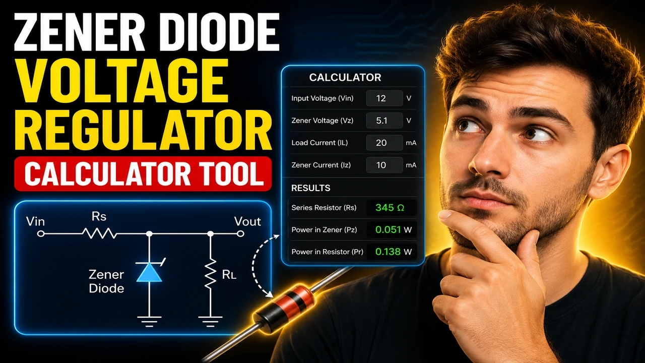
Use the Zener Diode Voltage Regulator Calculator Tool Use to estimate current, resistance, and power from supply, Zener, and load values before building a circuit.
Please complete this field to continue.
Please complete this field to continue.
Please complete this field to continue.
Please complete this field to continue.
Please complete this field to continue.
Please complete this field to continue.
Results
Zener Diode Voltage Regulator Calculator Tool Use
Quick answer: The Zener Diode Voltage Regulator Calculator is an electrical engineering calculator intended to help determine important voltage regulator circuit values, including Zener diode current, series resistor requirements, and power dissipation, using the circuit's supply voltage, desired regulated voltage, load conditions, and component parameters. The exact calculations available depend on the calculator's implemented inputs and formulas.
A Zener diode voltage regulator uses a reverse-biased Zener diode to maintain an approximately constant output voltage across a load when the diode operates within its specified breakdown-current range. A series resistor limits current from the supply, helping establish the operating conditions needed for voltage regulation.
The Zener Diode Voltage Regulator Calculator Tool Use page is intended for electronics students, hobbyists, technicians, and engineers who need to estimate circuit parameters before selecting components or building a shunt regulator. Since the actual calculator interface and its complete input specification have not been provided, the equations and worked examples below describe the standard Zener shunt-regulator method rather than verified implementation details of the live tool.
Key Takeaways
- Primary function: Evaluate standard Zener shunt voltage-regulator circuit parameters.
- Typical inputs: Supply voltage, Zener voltage, load current or load resistance, and series resistance.
- Typical results: Regulated output estimate, resistor current, Zener current, and component power dissipation.
- Best suited for: Preliminary circuit calculations and component-selection checks.
How to Use Zener Diode Voltage Regulator Calculator Tool Use?
- Enter the supply voltage: Specify the DC input voltage available to the regulator.
- Specify the Zener voltage: Enter the diode's nominal reverse-breakdown voltage, which approximates the regulated output voltage.
- Define the load: Enter the load current or load resistance, depending on the circuit information available.
- Provide the series resistor: Enter the existing resistor value if the calculator requests it, or calculate a suitable value using the standard equations below.
- Review the results: Check the current flowing through the Zener diode and load, along with resistor and diode power dissipation where those values are available.
Use the input fields and units actually presented by the live calculator. Do not assume that it supports every parameter listed here; the available fields have not been independently verified.
Input and Output Example
Consider a basic shunt regulator supplied by a 12 V DC source. The circuit uses a nominal 5.1 V Zener diode, a 330 Ω series resistor, and a load drawing 10 mA. Assume the Zener diode remains in breakdown and its voltage is approximately constant at 5.1 V.
Example Circuit Parameters
| Parameter | Value | Meaning |
|---|---|---|
| Supply voltage, Vs | 12 V | DC source voltage |
| Zener voltage, Vz | 5.1 V | Nominal regulated voltage |
| Series resistance, Rs | 330 Ω | Limits current from the supply |
| Load current, IL | 10 mA | Current consumed by the load |
Worked Calculation
1. Series-resistor current
IR = (Vs − Vz) / Rs
IR = (12 − 5.1) / 330 = 0.02091 A ≈ 20.91 mA
2. Zener current
IZ = IR − IL
IZ = 20.91 − 10 = 10.91 mA
3. Series-resistor power
PR = IR² × Rs
PR ≈ (0.02091)² × 330 ≈ 0.144 W
4. Zener power
PZ = VZ × IZ
PZ ≈ 5.1 × 0.01091 ≈ 0.0556 W
Expected theoretical result: The output is approximately 5.1 V under the stated assumptions, with approximately 10.91 mA flowing through the Zener diode. The resistor dissipates about 0.144 W, and the Zener diode dissipates about 0.056 W.
These figures are theoretical estimates, not verified output from the live calculator. Real results vary with Zener tolerance, dynamic resistance, temperature, supply variation, and load variation.
Zener Regulator Formula Reference
The following formulas describe the conventional Zener shunt-regulator circuit, in which the series resistor feeds a parallel combination of the Zener diode and load.
| Quantity | Formula | Purpose |
|---|---|---|
| Series current | IR = (Vs − VZ) / RS | Calculates current through the resistor |
| Load current | IL = VZ / RL | Estimates load current for a resistive load |
| Zener current | IZ = IR − IL | Determines current available to the diode |
| Resistor value | RS = (Vs − VZ) / (IL + IZ) | Estimates the resistance needed for a target current |
| Resistor power | PR = IR² × RS | Calculates series-resistor dissipation |
| Zener power | PZ = VZ × IZ | Calculates diode dissipation |
| Load power | PL = VZ × IL | Calculates power delivered to the load |
Variable definitions:
- Vs: DC supply voltage, in volts (V).
- VZ: Zener breakdown voltage, in volts (V).
- RS: Series resistance, in ohms (Ω).
- RL: Load resistance, in ohms (Ω).
- IR: Series-resistor current, in amperes (A).
- IZ: Zener current, in amperes (A).
- IL: Load current, in amperes (A).
- PR, PZ, PL: Resistor, Zener, and load power, in watts (W).
How the Zener Voltage Regulator Calculation Works
In the idealized circuit, the Zener diode is reverse-biased and connected in parallel with the load. Once the diode is operating in its breakdown region at the intended current, the output voltage remains approximately equal to its Zener voltage.
The series resistor drops the difference between the supply voltage and the regulated output. Its current divides between the Zener diode and the load. Therefore, the regulator only maintains the expected voltage when enough current remains for the diode to operate in breakdown without exceeding its current or power limits.
For a resistive load, the principal relationships are:
Resistor current: IR = (Vs − VZ) / RS
Current balance: IR = IZ + IL
Load current: IL = VZ / RL
These equations assume a simple DC shunt regulator and use the nominal Zener voltage as a constant. They do not independently account for diode dynamic resistance, the Zener voltage's test-current specification, temperature coefficients, wiring losses, or source impedance.
Important Edge Cases and Limitations
Insufficient Zener Current
If the load consumes nearly all the current supplied through the resistor, the Zener current can fall below the diode's required regulation current. The output voltage may then fall below its nominal value. A calculation that produces IZ less than or equal to zero indicates that the assumed regulated operating point is not feasible under the simple model.
Excessive Zener Power
At light load or no load, more current can flow through the Zener diode. Calculate its dissipation at the highest supply voltage and lowest load current, then compare it with the diode's permitted power under the actual thermal conditions.
Series-Resistor Heating
The resistor must tolerate the power dissipated across it. A theoretical result of 0.144 W does not automatically make a 0.125 W resistor suitable. Component selection should include a reasonable margin and account for ambient temperature, enclosure conditions, and manufacturer derating.
Supply and Load Variations
Evaluate both extremes: the lowest supply voltage with the highest load current for minimum Zener current, and the highest supply voltage with the lowest load current for maximum Zener current and power. A single nominal calculation is insufficient to establish regulation across a full operating range.
Invalid or Incomplete Inputs
Standard equations cannot produce a meaningful design result if essential parameters are missing, units are inconsistent, or the chosen supply voltage is not above the intended regulated voltage. Because the live tool's validation rules have not been supplied, its precise response to invalid entries is unknown.
Technical Assumptions and Component Selection
- Use a Zener diode rated for the expected reverse voltage, current, and power.
- Choose a resistor that limits current at maximum input voltage and minimum load.
- Verify that sufficient Zener current remains at minimum input voltage and maximum load.
- Account for component tolerances and thermal derating before building the circuit.
- Do not treat the nominal Zener voltage as perfectly constant across every current and temperature.
Technical Disclaimer: This explanation provides preliminary calculations for a conventional Zener shunt regulator. Verify the design against the selected diode and resistor datasheets, actual supply tolerances, load requirements, thermal conditions, and applicable electrical safety practices before constructing or deploying a circuit.
Author Information
Author Name: Daniel Mercer
Author Description: Electrical Engineering Technical Writer specializing in analog electronics, semiconductor circuits, and practical circuit calculations.
Technical Review: The formulas and worked example are based on standard DC circuit analysis for a Zener shunt regulator. The live calculator's implementation and validation behavior have not been independently verified.
