
Cable Voltage Drop Calculator Online For Wiring Design
Estimate cable voltage loss from current, cable length, conductor resistance, and supply voltage. Calculate voltage drop percentage and review wiring design needs.
Please complete this field to continue.
Please complete this field to continue.
Please complete this field to continue.
Please complete this field to continue.
Please complete this field to continue.
Please complete this field to continue.
Please complete this field to continue.
Please complete this field to continue.
Results
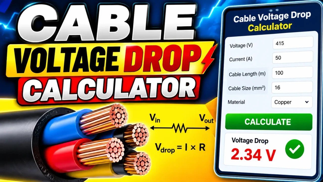
Cable Voltage Drop Calculator Online
Quick answer: A Cable Voltage Drop Calculator Online is an electrical engineering calculator used to estimate the voltage lost as current flows through a cable. By applying the circuit current, one-way cable length, conductor resistance, and circuit configuration, a voltage drop calculation determines the approximate voltage loss and helps assess cable performance under load.
The Cable Voltage Drop Calculator Online is intended for electricians, electrical engineers, installation contractors, technicians, and students who need to evaluate voltage loss in electrical wiring. Cable resistance causes the voltage available at the load to be lower than the supply voltage. This effect becomes more significant as cable length and load current increase.
Voltage drop calculations are useful when planning lighting circuits, distribution feeders, motor connections, solar installations, battery systems, and other electrical applications. The calculation method depends on the circuit type, conductor material, operating temperature, and the resistance or impedance data used. The results should therefore be interpreted according to the actual cable specification and installation conditions.
What Does Cable Voltage Drop Mean?
Cable voltage drop is the difference between the voltage supplied at the beginning of a cable run and the voltage available at the load end while current is flowing.
For example, if a circuit receives 230 V at its source and experiences a calculated voltage drop of 8 V, the approximate load-end voltage is 222 V. The voltage drop percentage expresses this loss relative to the nominal supply voltage.
- Voltage drop (V): The absolute voltage lost along the cable.
- Voltage drop (%): The voltage loss expressed as a percentage of the source voltage.
- Receiving-end voltage (V): The approximate voltage remaining at the load.
- Conductor resistance (Ω): The opposition to current flow through the conductor.
How to Use Cable Voltage Drop Calculator Online?
- Identify the circuit: Determine whether the installation uses DC, single-phase AC, or three-phase AC.
- Determine the cable length: Measure the one-way distance from the supply to the load and identify the length unit.
- Obtain the electrical data: Identify the load current, supply voltage, conductor material, cross-sectional area, and applicable resistance data.
- Calculate and evaluate: Use the calculator fields provided to obtain the voltage drop and percentage, then compare the result with the applicable design criteria.
The exact fields and displayed outputs depend on the implementation of the calculator. If conductor resistance is entered directly, use resistance values that match the selected cable, length unit, and operating conditions. If a cable size is selected instead, confirm which resistance or impedance data the calculation uses.
Input Parameters and Their Meaning
| Parameter | Unit | Why It Matters |
|---|---|---|
| Supply voltage | V | Provides the reference for calculating voltage drop percentage and load-end voltage. |
| Load current | A | Higher current generally produces a greater voltage drop for the same cable. |
| One-way cable length | m or ft | Longer cable runs generally have greater resistance. |
| Conductor resistance | Ω/m, Ω/km, or Ω/1,000 ft | Determines the resistive voltage loss for a specified length and current. |
| Conductor cross-sectional area | mm² or an applicable wire gauge | Helps identify the conductor size and its corresponding electrical resistance. |
| Circuit configuration | DC, single-phase, or three-phase | Determines the appropriate circuit factor and calculation method. |
| Power factor and reactance | Dimensionless and Ω | May be required for more detailed AC impedance calculations. |
Not every calculator accepts all these parameters. Always use the fields actually provided and check the method used to obtain the result.
Input and Output Example
Consider an illustrative single-phase, two-wire DC or resistance-only circuit calculation using a copper conductor. The example uses a representative resistance value and demonstrates the mathematics; it is not a claim about a measured result from the online tool.
Input assumptions:
- Supply voltage: 230 V
- Load current: 20 A
- One-way cable length: 30 m
- Conductor resistance: 7.41 Ω/km
- Circuit factor: 2, accounting for the outgoing and return conductors
Step 1 — Convert the resistance to the cable length:
Resistance of one conductor = 7.41 × 30 ÷ 1,000 = 0.2223 Ω.
Step 2 — Calculate the voltage drop:
Voltage drop = 2 × Current × One-way length × Resistance per unit length
Voltage drop = 2 × 20 × 30 × 7.41 ÷ 1,000 = 8.892 V.
Step 3 — Calculate the percentage drop:
Voltage drop (%) = (Voltage drop ÷ Supply voltage) × 100
Voltage drop (%) = (8.892 ÷ 230) × 100 = 3.87%, approximately.
Step 4 — Estimate the receiving-end voltage:
Receiving-end voltage = 230 − 8.892 = 221.108 V, or approximately 221.11 V.
This simplified example assumes constant current and resistance, with no additional allowance for temperature changes, AC reactance, or other installation effects.
Voltage Drop Formula and Methodology
The voltage drop formula depends on the circuit configuration and the electrical data available. For a resistance-only calculation, a general form is:
ΔV = k × I × L × R
- ΔV: Voltage drop in volts.
- k: Circuit factor, commonly 2 for a two-wire DC or single-phase circuit and √3 for a balanced three-phase circuit when using the corresponding line-to-line convention.
- I: Load current in amperes.
- L: One-way cable length.
- R: Conductor resistance per unit length, using units consistent with L.
When resistance is expressed in ohms per kilometre and length is expressed in metres, the formula becomes:
ΔV = k × I × L × R ÷ 1,000
For percentage voltage drop:
Voltage drop (%) = (ΔV ÷ Vs) × 100
For estimated receiving-end voltage:
Vload ≈ Vs − ΔV
Here, Vs is the source voltage. These expressions are simplified resistance-based relationships. For AC systems where conductor reactance and load power factor are significant, the calculation may need the cable impedance components and the appropriate AC voltage-drop equation.
Technical Reference: Circuit Type and Calculation Factor
| Circuit type | Typical factor | Important consideration |
|---|---|---|
| DC, two-wire | 2 | Accounts for the outgoing and return conductors when length is measured one way. |
| Single-phase AC, two-wire | 2 in a simplified resistance-only model | For detailed AC calculations, include power factor and cable reactance where applicable. |
| Balanced three-phase AC | √3 in a simplified line-to-line model | Use the appropriate phase and voltage convention for the circuit. |
| AC circuit with material impedance data | Depends on circuit configuration | Resistance, reactance, power factor, and operating conditions may affect the result. |
The factor alone does not define a complete voltage-drop calculation. The resistance or impedance units, conductor arrangement, voltage convention, and selected formula must be consistent.
Factors That Affect Cable Voltage Drop
- Cable length: Increasing the length increases the conductor resistance when other conditions remain unchanged.
- Load current: Voltage drop generally increases in proportion to current in a fixed-resistance model.
- Conductor material: Copper and aluminium have different electrical resistance characteristics.
- Cable cross-sectional area: A larger conductor generally has lower resistance for the same material and length.
- Operating temperature: Conductor resistance changes with temperature, affecting voltage-drop estimates.
- AC impedance: Reactance and power factor can influence voltage drop, particularly in longer AC circuits and certain load conditions.
- Parallel conductors: Properly configured parallel conductors can reduce the effective impedance, but current sharing and installation requirements must be considered.
Understanding the Results
A voltage-drop result should be evaluated in both volts and percentage. A drop of 5 V represents approximately 2.17% on a 230 V supply, but approximately 4.17% on a 120 V supply. The same absolute voltage loss can therefore have different implications for different systems.
As an initial design reference, electrical guidance commonly uses voltage-drop targets such as 3% for branch circuits and 5% for combined feeder and branch circuits in certain installations. These figures are not universal limits for every country, installation, or circuit type. Verify the applicable electrical code, project specification, equipment requirements, and local authority rules before accepting a design.
Edge Cases and Limitations
- Zero current: A steady-state resistance-based model produces zero voltage drop when current is zero, excluding other system effects.
- Zero or negative cable length: Confirm that the entered length represents a valid physical run and is greater than zero for normal cable calculations.
- Unit mismatch: Combining metres with resistance per kilometre without conversion produces an incorrect result.
- Incorrect length convention: If a formula already includes a return-path factor, entering the round-trip length instead of the one-way length may count the return path twice.
- Operating temperature: Resistance values specified at a reference temperature may not represent actual operating conditions.
- Motor starting and changing loads: A steady-state calculation does not necessarily predict transient voltage dips or startup performance.
- Three-phase imbalance: Simplified balanced three-phase formulas may not adequately represent an unbalanced system.
- Unknown cable data: An assumed resistance value can materially affect the estimate; use manufacturer data or applicable engineering tables when available.
Because the precise validation rules of the calculator have not been established here, invalid-input handling and supported operating ranges should be confirmed against the live tool rather than assumed.
Technical Guidance and References
For more detailed calculation guidance, consult the following technical references:
- Electrical Installation Guide — Calculation of voltage drop in steady load conditions. This reference explains voltage-drop relationships for single-phase and balanced three-phase circuits, including resistance, reactance, and power factor.
- Southwire — Power Cable Installation Guide. Chapter 6 discusses cable voltage-drop equations and the effects of AC impedance.
Technical Disclaimer
This calculator page describes voltage-drop estimation principles and illustrative calculations. A calculated voltage drop does not by itself establish that a cable is safe or correctly sized. Final cable selection must also consider current-carrying capacity, insulation temperature rating, installation method, ambient temperature, grouping, short-circuit withstand, protective-device coordination, earthing, and applicable electrical regulations. Have consequential electrical designs checked by a qualified electrical professional.
Author
Author Name: Daniel R. Mercer
Author Description: Electrical Engineering Content Specialist focused on conductor sizing, circuit calculations, and electrical installation fundamentals.
Technical Review: The calculation methodology described here distinguishes resistance-only voltage-drop estimates from more detailed AC impedance calculations. The worked example uses explicitly stated assumptions and should be verified against the selected cable's technical data before practical use.
