
Solar Panel Mounting Rail Length Calculator – Rail Sizing
Calculate solar panel mounting rail length from panel count, rail-parallel dimensions, panel gaps, and end allowances to plan a row layout before installation.
Please complete this field to continue.
Please complete this field to continue.
Please complete this field to continue.
Please complete this field to continue.
Results
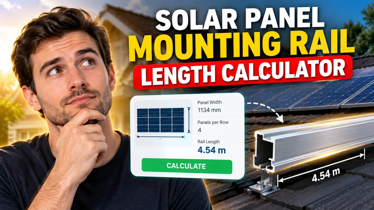
Solar Panel Mounting Rail Length Calculator
Quick answer: The Solar Panel Mounting Rail Length Calculator is an engineering calculator concept for estimating the mounting rail length needed for a row of solar panels. The estimate depends on the panel dimension along the rail, the number of panels, the gaps between adjacent panels, and the required rail allowance at both ends.
Accurate solar rail sizing starts with the panel layout and the mounting system's installation requirements. A rail must accommodate the module widths, mid-clamp spacing, and end-clamp or end-cap allowances. This calculator page is intended to help installers, solar designers, contractors, and homeowners estimate the total rail length before selecting stock rail sections or planning rail connections.
TL;DR / Key Takeaways
- Primary function: Estimate the mounting rail length for a row of solar panels.
- Key inputs: Panel count, panel dimension along the rail, inter-panel gap, and end allowances.
- Core output: Estimated total rail length per rail run.
- Important distinction: Required rail length is not the same as the number of rails, roof attachment spacing, or structural capacity.
How to Use Solar Panel Mounting Rail Length Calculator?
- Enter the number of panels. Count the modules installed side by side along one continuous rail run.
- Choose the correct panel dimension. Use the module width when the layout places the panel's width along the rail, or its length when the layout places its length along the rail.
- Enter the panel gap. Specify the clear spacing or clamp allowance between adjacent modules according to the selected racking system.
- Enter the end allowances. Include the manufacturer's specified rail extension for end clamps, end caps, or other required hardware.
- Calculate the rail length. Review the total for one rail run, then account separately for the number of parallel rail runs and available stock lengths.
The exact fields and calculation options depend on the calculator implementation. The methodology below describes a transparent general estimation model; it does not establish that every listed input is available in the live tool.
Input and Output Example
Consider a row of six solar panels. Assume each panel measures 1,134 mm along the rail, the specified gap between adjacent panels is 20 mm, and the system requires a 30 mm allowance at each end.
Example inputs
| Parameter | Example value |
|---|---|
| Number of panels | 6 |
| Panel dimension along rail | 1,134 mm |
| Number of inter-panel gaps | 5 |
| Gap per adjacent pair | 20 mm |
| Left end allowance | 30 mm |
| Right end allowance | 30 mm |
Calculation
Total panel width = 6 × 1,134 = 6,804 mm.
Total gap allowance = (6 − 1) × 20 = 100 mm.
Total end allowance = 30 + 30 = 60 mm.
Estimated rail length = 6,804 + 100 + 60 = 6,964 mm, or 6.964 m.
This result represents the calculated length of one rail run under the stated assumptions. If the design uses two parallel rails beneath each panel row, the corresponding preliminary combined rail quantity is 13.928 linear metres before accounting for cutting waste, splice arrangements, stock lengths, and system-specific constraints.
Solar Panel Mounting Rail Length Formula
A general formula for a straight row of equally sized modules is:
L = (N × D) + ((N − 1) × G) + A + B
- L = estimated total rail length.
- N = number of panels along the rail.
- D = panel dimension parallel to the rail.
- G = specified allowance for each gap between adjacent panels.
- A = required allowance at the first end.
- B = required allowance at the opposite end.
For a row of N panels, there are N − 1 internal gaps, not N. The two end allowances are added separately. If both ends use the same allowance E, the formula simplifies to L = (N × D) + ((N − 1) × G) + (2 × E).
Keep all dimensions in one unit system. Convert inches to millimetres or feet to metres before combining values. Do not add clamp dimensions twice if the gap input already represents the full allowance required by the mounting-system instructions.
Rail Length Reference Table
The following examples use a panel dimension of 1,134 mm, a 20 mm allowance between adjacent panels, and 30 mm at each end. These are illustrative inputs, not universal solar mounting specifications.
| Panels per row | Panel width total | Gap allowance | End allowance | Estimated rail length |
|---|---|---|---|---|
| 2 | 2,268 mm | 20 mm | 60 mm | 2,348 mm |
| 3 | 3,402 mm | 40 mm | 60 mm | 3,502 mm |
| 4 | 4,536 mm | 60 mm | 60 mm | 4,656 mm |
| 5 | 5,670 mm | 80 mm | 60 mm | 5,810 mm |
| 6 | 6,804 mm | 100 mm | 60 mm | 6,964 mm |
| 8 | 9,072 mm | 140 mm | 60 mm | 9,272 mm |
| 10 | 11,340 mm | 180 mm | 60 mm | 11,580 mm |
Use this table as a quick reference for the stated assumptions only. A different module dimension, clamp design, rail profile, or end-cap requirement will change the result.
How Panel Orientation Affects Rail Length
Panel orientation changes which module dimension runs along the rail. In portrait orientation, the module's shorter side commonly runs across the row, while in landscape orientation, the longer side commonly runs across the row. However, the actual dimension to use depends on the orientation of the panels relative to the rail, not merely the orientation label.
For example, if a module measures 1,722 × 1,134 mm, using 1,134 mm rather than 1,722 mm for the rail-parallel dimension changes the calculated length substantially. Confirm the physical layout drawing and the mounting-system manual before entering the dimension.
Clamp Allowances and Mounting System Compatibility
Mid-clamps sit between adjacent modules, while end clamps secure the modules at the ends of a row. The required allowance depends on the actual clamp and rail system. Manufacturer instructions can specify different inter-module gaps and end extensions.
| Calculation component | What to enter | What to verify |
|---|---|---|
| Module dimension | Width or length parallel to the rail | Module drawing and layout orientation |
| Inter-panel gap | Required allowance per adjacent pair | Mid-clamp and module-spacing instructions |
| First-end allowance | Required length beyond the first module edge | End clamp and end-cap requirements |
| Opposite-end allowance | Required length beyond the last module edge | End clamp and end-cap requirements |
| Rail splice | Connection arrangement when one rail is insufficient | Approved splice location and connector instructions |
For a system-specific reference, see the ESDEC ClickFit EVO installation guide. Its rail-sizing instructions specify particular module-gap and end-allowance values for the system described in that document. Those values should not be transferred automatically to another mounting system.
The IronRidge rail assembly reference also illustrates why clamp spacing and end allowances must be matched to the selected hardware. Consult the current instructions for the exact products being installed.
How the Calculation Works
- Multiply the panel dimension parallel to the rail by the number of panels.
- Multiply the inter-panel allowance by the number of internal gaps, which is one fewer than the panel count.
- Add the allowances required at both rail ends.
- Use the resulting length to plan rail sections and connections according to the mounting system's approved configuration.
This formula estimates the geometric length needed for the panel row and its specified clamp allowances. It does not determine whether a rail is structurally adequate, how many roof attachments are required, the permitted cantilever, wind or snow loading, or the correct splice position.
Edge Cases and Limitations
- One panel: There are zero inter-panel gaps. The estimate is the panel dimension plus both end allowances.
- Zero panels: A zero-panel input does not describe a usable mounting row and should not be treated as a valid installation result.
- Missing gap allowance: Omitting the gap may underestimate the required length when the selected clamp system requires space between modules.
- Unequal modules: For panels with different dimensions, add each individual rail-parallel dimension rather than multiplying one dimension by the entire count.
- Mixed units: Convert every input to the same unit before calculating.
- Rail stock lengths: A calculated length may not match a commercially available rail section. Determine the permitted combination of sections and approved connectors separately.
- End overhang and attachment spacing: The geometric formula does not establish allowable rail overhang or attachment spacing. Follow the selected system's structural tables and installation instructions.
- Different rail runs: Rows with different panel counts or orientations need separate calculations.
Technical Disclaimer
This formula provides a preliminary rail-length estimate based on the entered dimensions and allowances. It is not a structural design calculation or a substitute for the selected mounting system's engineering documentation. Before purchasing or cutting rails, verify the module dimensions, clamp requirements, end allowances, connector compatibility, support locations, allowable spans, cantilevers, and site-specific wind and snow loads with the applicable manufacturer documentation and a qualified solar professional.
Author
Author Name: Michael Turner
Author Description: Renewable Energy Systems Technical Writer focused on photovoltaic mounting layouts, installation documentation, and solar-system component planning.
Technical Review: The calculation methodology is presented as a general geometric estimate. Confirm all system-specific dimensions, structural limits, and installation requirements against the selected manufacturer's current documentation before applying the result on site.
